
Tape muscle

a technology of tape muscles and tape muscles, applied in the field of tape muscles, to achieve the effect of improving clamping force and low cos

Inactive Publication Date: 2012-09-13
VRANISH JOHN M
View PDF2 Cites 9 Cited by
  • Summary
  • Abstract
  • Description
  • Claims
  • Application Information

AI Technical Summary

Benefits of technology

[0011]It is a principal object of the present invention to provide a practical artificial muscle robot system whereby multiple actuators can be moved and positioned in coordination with each other, with independent, motion in each, by electrical means and by using drive apparatus sufficiently compact to fit on the forearm of an average sized human. It is also a principal object of the present invention to move and position each actuator with force, speed and precision using flexible tape tendons in tension and to be capable of holding position with power off. It is a further objective of the present invention to arrange the multiple tape tendons in open ended loops wherein the open ends of each loop can move without interference from the other tape tendons, wherein, each open end tape tendon in a loop is independently moved by grasp and pull coordinated actions, performed by a Clamp module and Clamp & Pull module tandem, acting directly on the tape tendon and the open ends move in equal and opposite directions. It is an objective of the present invention to camp each tape with mechanical advance using elastic bending in the tape. It is an object of the present invention to provide enhanced clamping force through tape small angle bending mechanical advantage and release through tape spring return. It is an object of the present invention to use small angle bending in the Clamp & Drive module to pull each clamped tape with mechanical advantage and to spring return the Clamp & Drive module with mechanical advantage. It is an object of the present invention to, individually, clamp each tape to the Clamp module or release it from the Clamp module using a dedicated through channel for each tape with the separation between channels in the Clamp module small. It is an object of the present invention to, individually, clamp each tape to the Clamp & Drive module or release it from the Clamp & Drive module using a dedicated through channel for each tape with the separation between channels in the Clamp & Drive module small. It is an object of the present invention to use Charge-Driven Electrostatic Induction to individually power each clamp and pull motion with adequate force, power and speed, within the tight confines of the individual through channels and the Drive & Return modules. It is an option of the present invention to use construction methods and materials that are low cost and simple.

Problems solved by technology

There is a great amount of prior art in artificial muscles, but mostly is in the research stage with very few commercial products available.

Method used


Image

  • Tape muscle
  • Tape muscle
  • Tape muscle

Examples


Embodiment Construction

[0033]The invention will now be described in more detail by way of example with reference to the embodiment(s) shown in the accompanying figures. It should be kept in mind that the following described embodiments are only presented by way of example and should not be construed as necessarily limiting the inventive concept to any particular physical configuration.

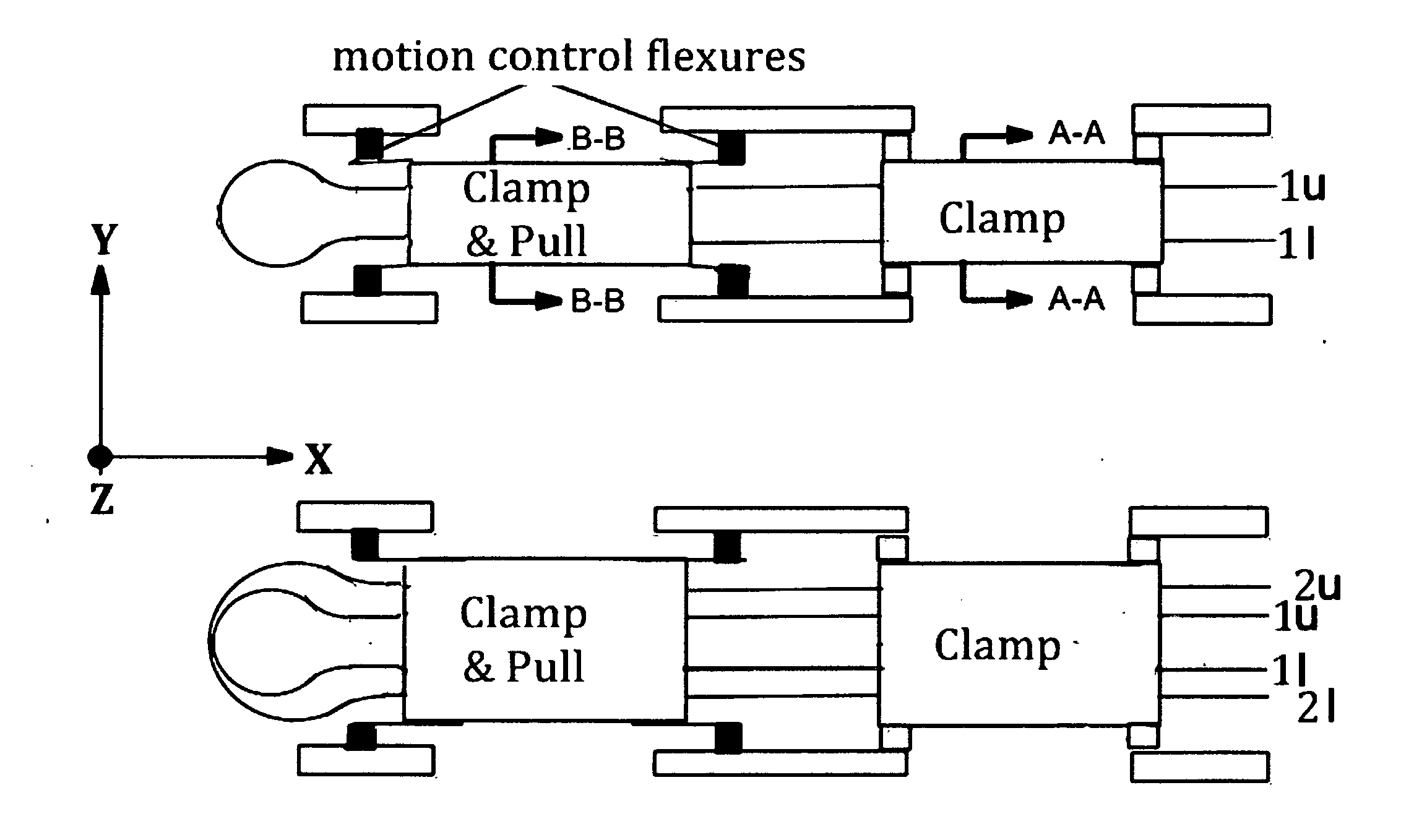
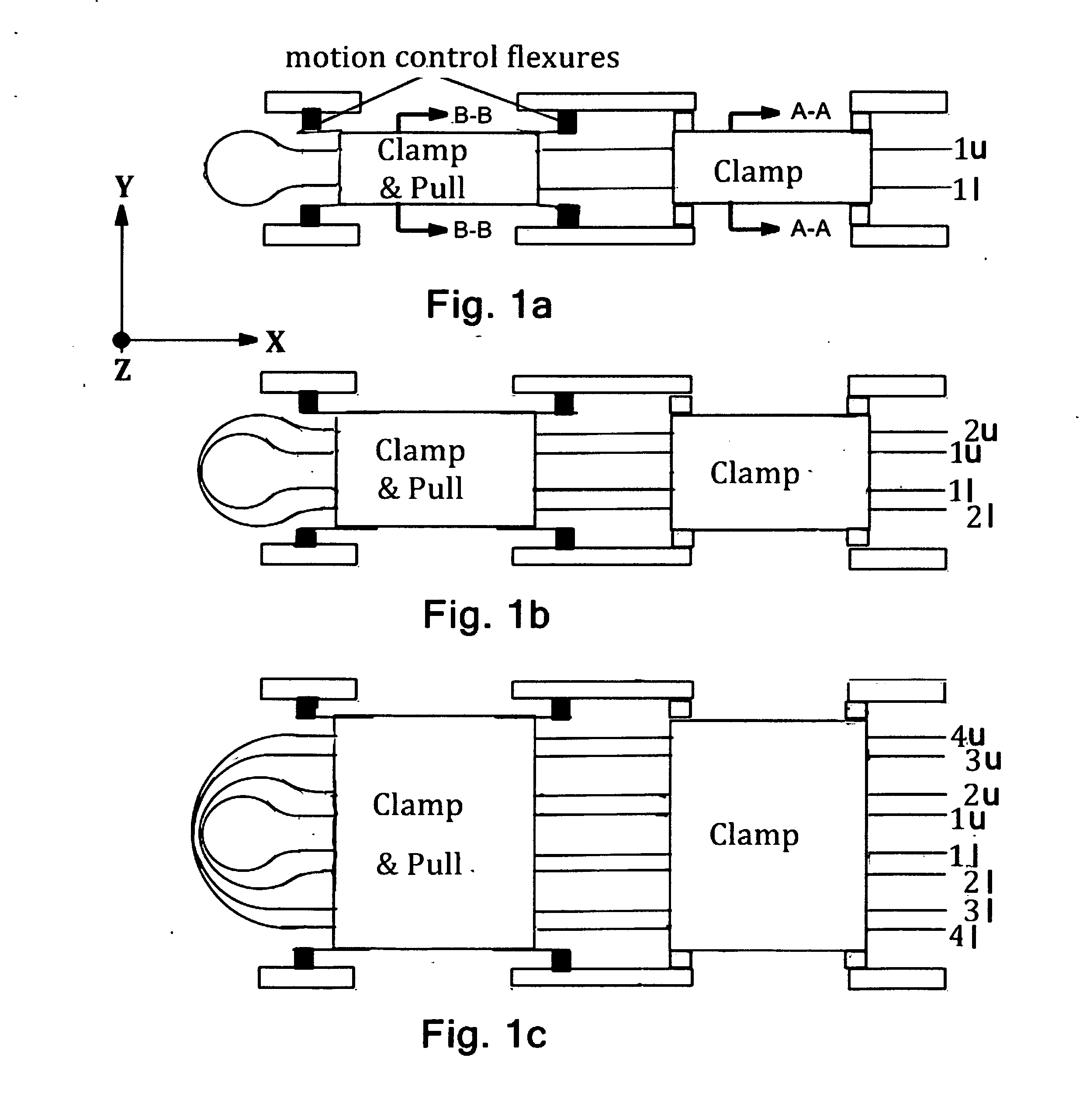
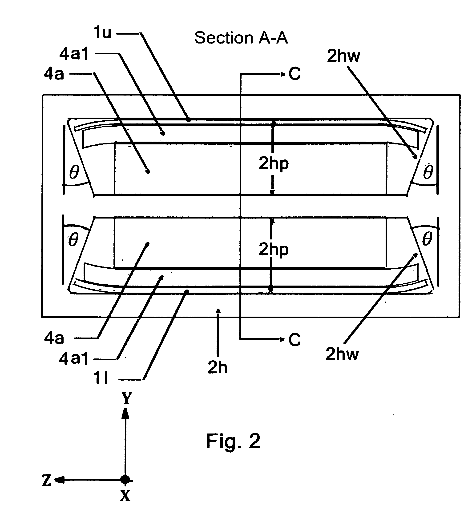
[0034]In accordance with the present invention, a Tape Muscle includes: One or more Tape Tendons, A Clamp module, a Clamp & Drive module, An Electric Drive system and a Controller. Each Tape Tendon includes a Tape with a flexible Tendon attached to each end. The Set of Tape Tendons are arranged in nested, open ended Tape Loops (1, 2, 3, 4), with each Tape Loop elastically bent in a turn-around loop with its open end segments each extending away from the turn-around parallel to each other (1u and 1l for 1, 2u and 2l for 2, 3u and 3l for 3, 4u and 4l for 4). The turn-around sections of each Tape Loop are nested inside each oth...


PUM


Abstract

A Tape Muscle is described where multiple tape loops are independently driven by synchronized grasp and pull actions from a tandem of Clamp, Clamp & Drive modules. Each tape loop is elastically bent, with its open ends threaded through individual passageways in both modules. Tape loops are nested inside each other with all tape open ends on the same side. Each loop moves its open ends in equal, opposite directions, while the loop position remains fixed. Tape movements do not interfere with each other. The open ends of each loop attach to a shared appendage, which is pulled back and forth using tensile forces. Drive and hold forces use small angle flexure bending mechanical advantage and high force density electrostatic induction methods. Tape speed results from high frequency clock speed and novel hand-off methods. Governing equations, design details and performance estimates are provided.

Description

[0001]The U.S. patent application claims the priority of U.S. Provisional Application No. 61 / 462,714 filed on Feb. 7, 2011.CROSS REFERENCE TO RELATED APPLICATION[0002]The inventions related to three (3) inventions shown and described in Vranish, J. M., Linear Tape Motor, U.S. Pat. No. 7,989,992B2 Aug. 2, 2011, Vranish, J. M., Stepping Flexures, U.S. Pat. No. 7,504,921, Mar. 17, 2009, (The rights to this invention are held by the United States Government.), Vranish, J. M., Charge-Driven Electrostatic Inductance, patent application filed Oct. 18, 2011, U.S. PTO Ser. No. 13 / 317,373 and Vranish, J. M., Device, System and Method for a Sensing Electric Circuit, U.S. Pat. No. 7,622,907, Nov. 24, 2009. [“Driven Ground”] (The rights to this invention are held by the United States Government.). The teachings of these related applications are herein meant to be incorporated by reference.ORIGIN OF THE INVENTION[0003]The invention was made by John M. Vranish as President of Vranish Innovative Te...

Claims


Application Information

Patent Timeline
IPC IPC(8): H02N1/00
CPCH02N1/00B25J9/1075
Inventor VRANISH, JOHN M.
Owner VRANISH JOHN M
Learn More