

Transmission system and relay device
a relay device and transmission system technology, applied in the field of power supply and reception, can solve the problems of failure to disclose the power supply to the relay device (such as the cable or repeater device) connected between the sink and the source device, and achieve the effect of avoiding the failure of the relay device to disclose the power supply to the relay devi
- Summary
- Abstract
- Description
- Claims
- Application Information
AI Technical Summary
Benefits of technology
Problems solved by technology
Method used
Image

Examples
embodiment 1
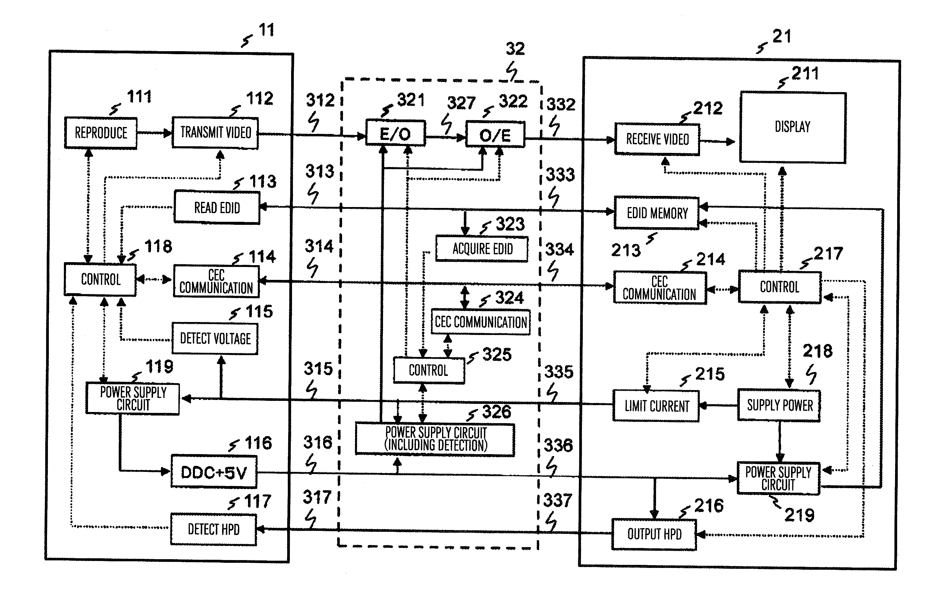
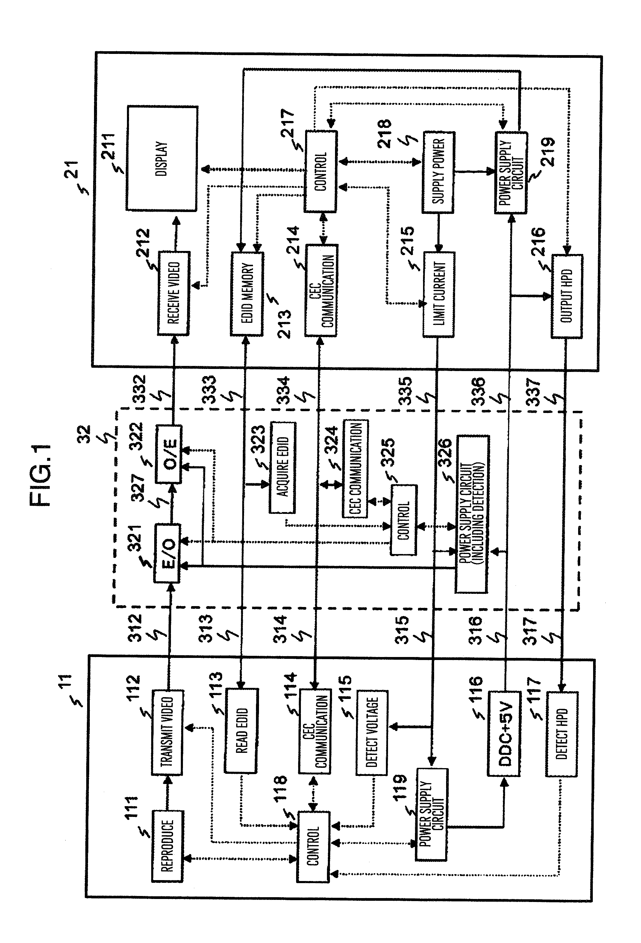
[0027]FIG. 1 is a block diagram showing an example of a transmission system of this embodiment, in which a source device 11 is connected to a sink device 21 via a cable 32, a power is supplied from the sink device to the source device, and a video signal is transmitted from the source device to the sink device.
[0028]The source device 11 is a video signal transmitting device such as a disk player, a disk recorder, a semiconductor recorder, a broadcasting receiver, a game machine, or a personal computer (PC). The source device 11 has a reproducer 111 for reproducing a video signal from data obtained from a storage medium such as an optical disk, a magnetic recording disk or a semiconductor memory or from a network; a video transmitter 112; an EDID (Extended Display
[0029]Identification Data) reader 113; a CEC (Consumer Electronics Control) communication unit 114; a voltage detector 115; a DDC (Display Data Channel) +5V supplier 116; an HPD (Hot Plug Detect) detector 117; a controller 1...
embodiment 2
[0072]Another embodiment of the transmission system in accordance with the present invention will be explained by referring to FIGS. 6 and 7. FIG. 6 is a block diagram of a part of a cable. A cable 34 is replaced by the cable 32 of FIG. 1, and includes a source device 11 and a sink device 21 both having similar structures to those in FIG. 1, and therefore the structures are not illustrated.
[0073]In FIG. 6, blocks having the same or equivalent functions are denoted by the same reference numerals. FIG. 6 is different from FIG. 1 in that a switch 341 is added between DDC terminals 313 and 333 for reading out EDID information; a utility terminal 315 is separated from a utility terminal 335, power supply circuits 343 and 326 are provided to the respective separated utility terminals; a DDC+5V terminal 316 is separated from the DDC+5V terminal 336 and an DDC+5V terminal 317 is separated from an DDC+5V terminal 337, an HPD output 344, an HPD detector 346, and a DDC+5V supplier 345 are adde...
embodiment 3
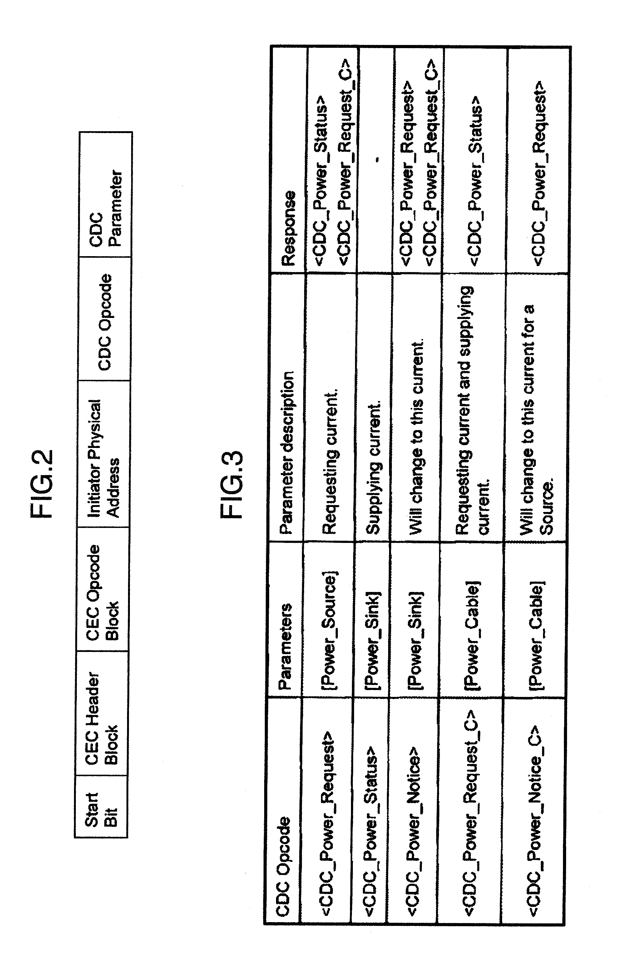
[0094]A flexible embodiment capable of adjusting a current supply amount stepwise will be shown. In the present embodiment, a block diagram of a transmission system, a message structure and a message example are substantially the same as those in FIGS. 1, 2 and 3 explained in the embodiment 1, and explanation thereof is omitted.
[0095]In place of parameters in FIG. 4, message parameters defined in FIGS. 8, 9 and 10 are used. A maximum current use amount [Source Current] for a source device a maximum current use amount [Cable_Current] for a cable are prepared respectively to have 5 sorts of 125 mA units in a range of 0 and 500 mA and a type of 5 mA as a standby mode. A maximum current supply amount [Sink_Current] for a sink device are set to be stepwise incremented by 25 mA so that 25 mA can be incrementally added as a standby current.
[0096]In this case, “0 mA” in [Sink_Current] indicates that a current supply capability is smaller than 25 mA, and has no capability of supplying the st...
PUM
 Abstract
Description
Claims
Application Information