[0006]The temperature of a liquid crystal panel sometimes varies depending on positions on the liquid crystal panel. For example, in a liquid
crystal display device including a backlight unit having a
light source at the edge of the backlight unit, the temperature of a portion (area) close to the edge of the liquid crystal panel is easily increased compared to those of the other areas. If the temperature of each area can be detected, control with higher accuracy is possible. However, when the same number of temperature sensors as areas are used, the cost of the liquid
crystal display device is increased.
[0007]It is an object of the invention to provide a liquid
crystal display device in which a temperature of each of plural areas defined on a liquid crystal panel can be obtained with a small number of temperature sensors.
[0009]In one aspect of the invention, the controller may use a plurality of relation formulas defined by the temperature relation information to thereby estimate the temperatures of the plurality of areas, wherein each of the plurality of relation formulas represents the relation between the output value of the at least one temperature sensor and the temperature of each of the plurality of areas. According to this aspect, a continuously changing value can be calculated as the temperature of each of the areas, which can increase the accuracy of
estimation of temperature. In this aspect, the memory may have a plurality of coefficients stored therein as the temperature relation information, wherein the plurality of coefficients is associated with the plurality of areas respectively, and the plurality of relation formulas may be defined by a fundamental relation formula to which the plurality of coefficients are applied, respectively. According to this aspect, it is no more necessary to store in the memory the plural relation formulas respectively corresponding to the plural areas. For example, the plural relation formulas respectively corresponding to the plural areas can be obtained from one fundamental relationship.
[0010]In another aspect of the invention, the controller may determine, the controller may determine, based on information changing according to an elapsed time since the start of driving of the liquid crystal
display device, whether or not a present time falls in a steady-state period about temperature of the liquid crystal panel, and the controller may execute, as a process for estimating temperatures of the plurality of areas, processes different depending on whether the present time falls in the steady-state period or the present time does not fall in the steady-state period. According to this aspect, even if the present time is not the steady-state period, the temperature of the liquid crystal panel can be properly estimated. In this aspect,
two temperature sensors disposed away from each other may be included as the at least one temperature sensor, and the controller may use, as the information changing according to the elapsed time since the start of driving of the liquid crystal
display device, a difference in output value between the
two temperature sensors. According to this aspect, it can be easily determined whether or not the present time corresponds to the steady-state period.
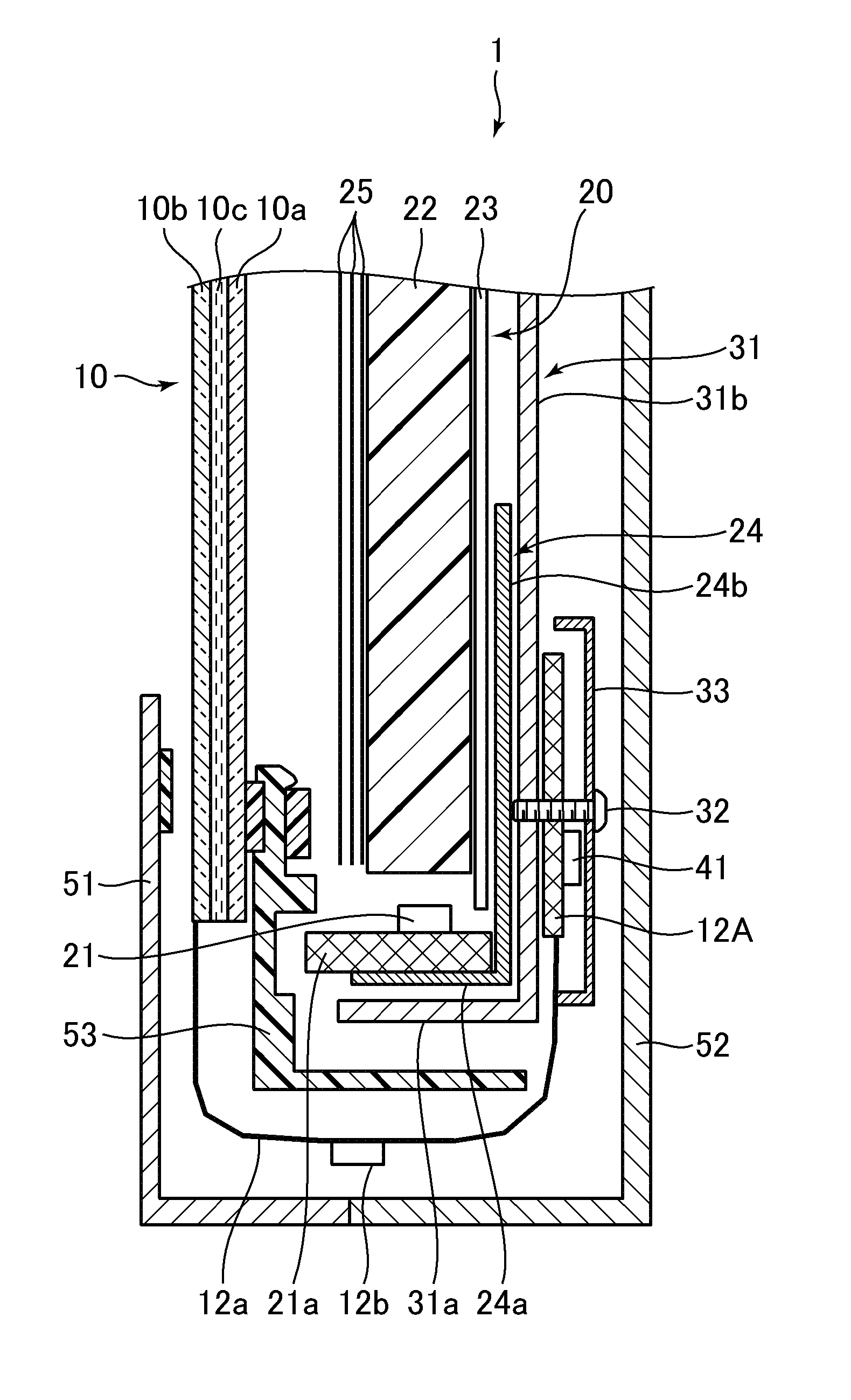
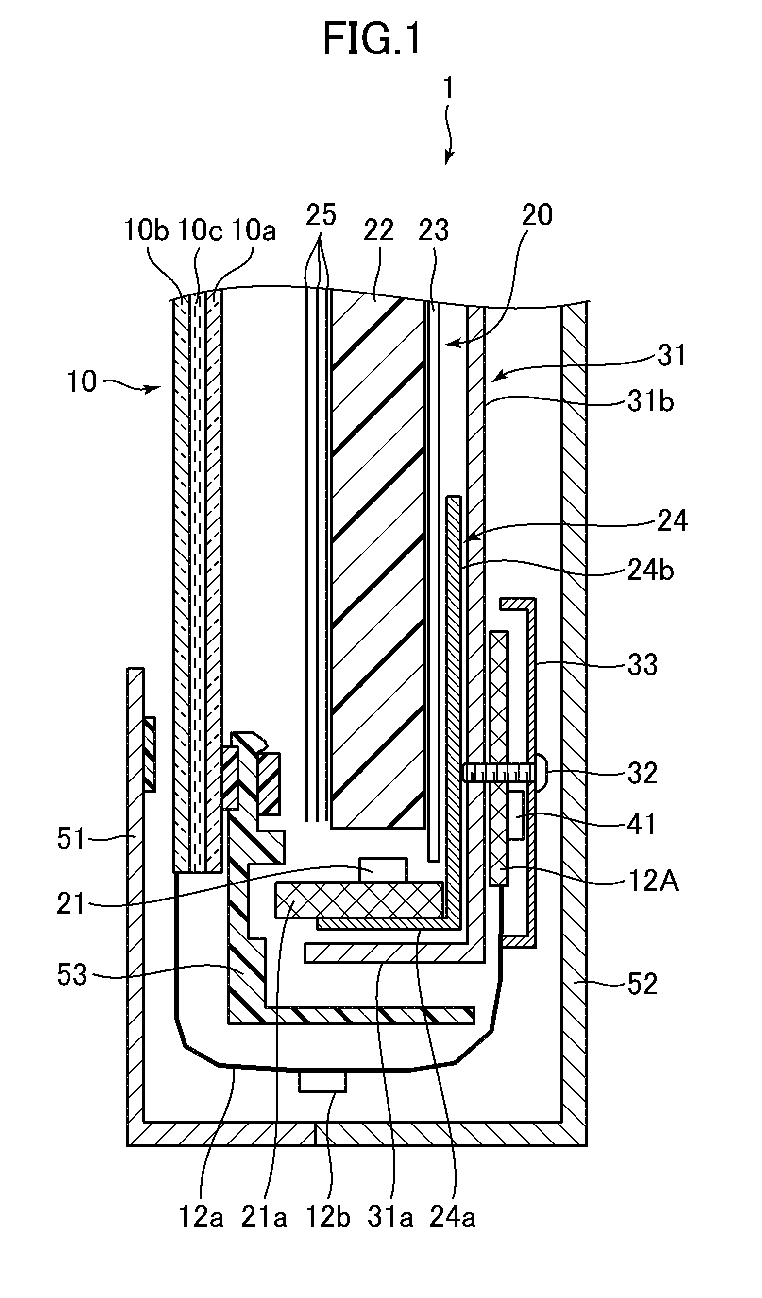
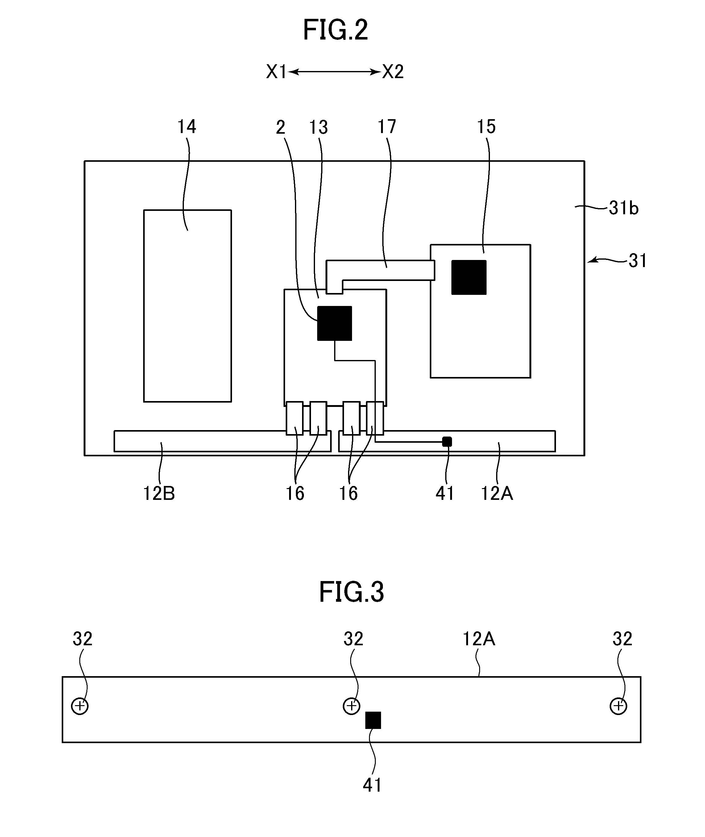
[0011]In still another aspect of the invention, the liquid crystal display device may further include a backlight unit including a
light guide plate and a
light source disposed at least one side of the
light guide plate. According to this aspect, especially the process for estimating a temperature for each of the plural areas is effectively operated. Moreover, in this aspect, the liquid crystal display device may further include a circuit board having the at least one temperature sensor attached thereon and disposed along the at least one side of the
light guide plate. By doing this, a correlation between the output value of the temperature sensor and the temperature of the liquid crystal panel can be increased. The liquid crystal display device may further include a rear frame made of
metal and covering the rear side of the backlight unit, wherein the circuit board is fixed to the rear frame. According to this configuration, the correlation between the output value of the temperature sensor and the temperature of the liquid crystal panel can be further increased. Moreover, the liquid crystal display device may further include a plurality of circuit boards, wherein the at least one temperature sensor is attached to one of the plurality of circuit boards which is closest to the
light source. According to this configuration, the correlation between the output value of the temperature sensor and the temperature of the liquid crystal panel can be further increased. Moreover, in this aspect, the light source may include plural LEDs. When LEDs are used in this manner, especially the process for estimating the temperature for each of the plural areas is effectively operated.

