Lens holder drive apparatus, and camera equipped therewith

a technology of lens holder and drive apparatus, which is applied in the direction of camera focusing arrangement, printers, instruments, etc., can solve the problems of complex structure, inconvenient miniaturization, and difficulty in applying a sensor-shifting type of camera-shake correction apparatus to a small camera

Active Publication Date: 2012-09-13
MITSUMI ELECTRIC CO LTD
View PDF5 Cites 137 Cited by
  • Summary
  • Abstract
  • Description
  • Claims
  • Application Information

AI Technical Summary

Benefits of technology

[0072]According to the present invention, the use of a barrel-shifting method, in contrast to a conventional optical camera-shake correction method (lens shifting, sensor shifting, or optical unit tilting), enables the size (mainly the height) of a lens holder drive apparatus to be made smaller.

Problems solved by technology

Consequently, it is difficult to apply a sensor-shifting type of camera-shake correction apparatus to a small camera for mobile phone use from a size (external shape and height) standpoint.
Therefore, a problem with an image blurring correction apparatus (camera-shake correction apparatus) having such a structure is that its structure is complex and it is not suitable for miniaturization.
That is to say, as with an above-described sensor-shifting type of camera-shake correction apparatus, it is difficult to apply a lens-shifting type of camera-shake correction apparatus to a small camera for mobile phone use from a size (external shape and height) standpoint.
However, a problem with this software method disclosed in Patent Literature 10 is that image quality degrades in comparison with an above-described optical method.
Also, a software method has the disadvantage of taking a long time, since it includes both imaging time and software processing time.

Method used


Image

  • Lens holder drive apparatus, and camera equipped therewith
  • Lens holder drive apparatus, and camera equipped therewith
  • Lens holder drive apparatus, and camera equipped therewith

Examples


first embodiment

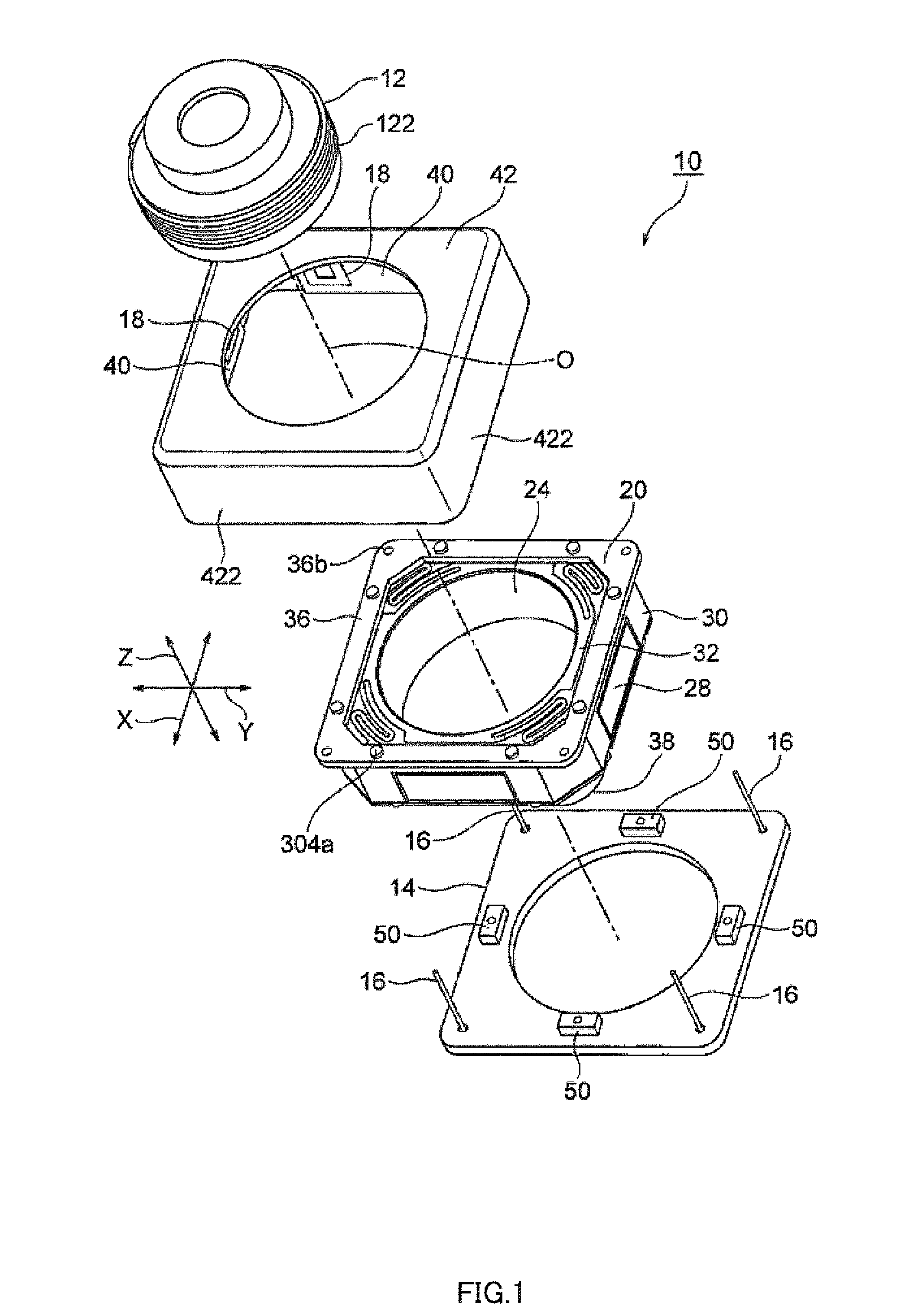
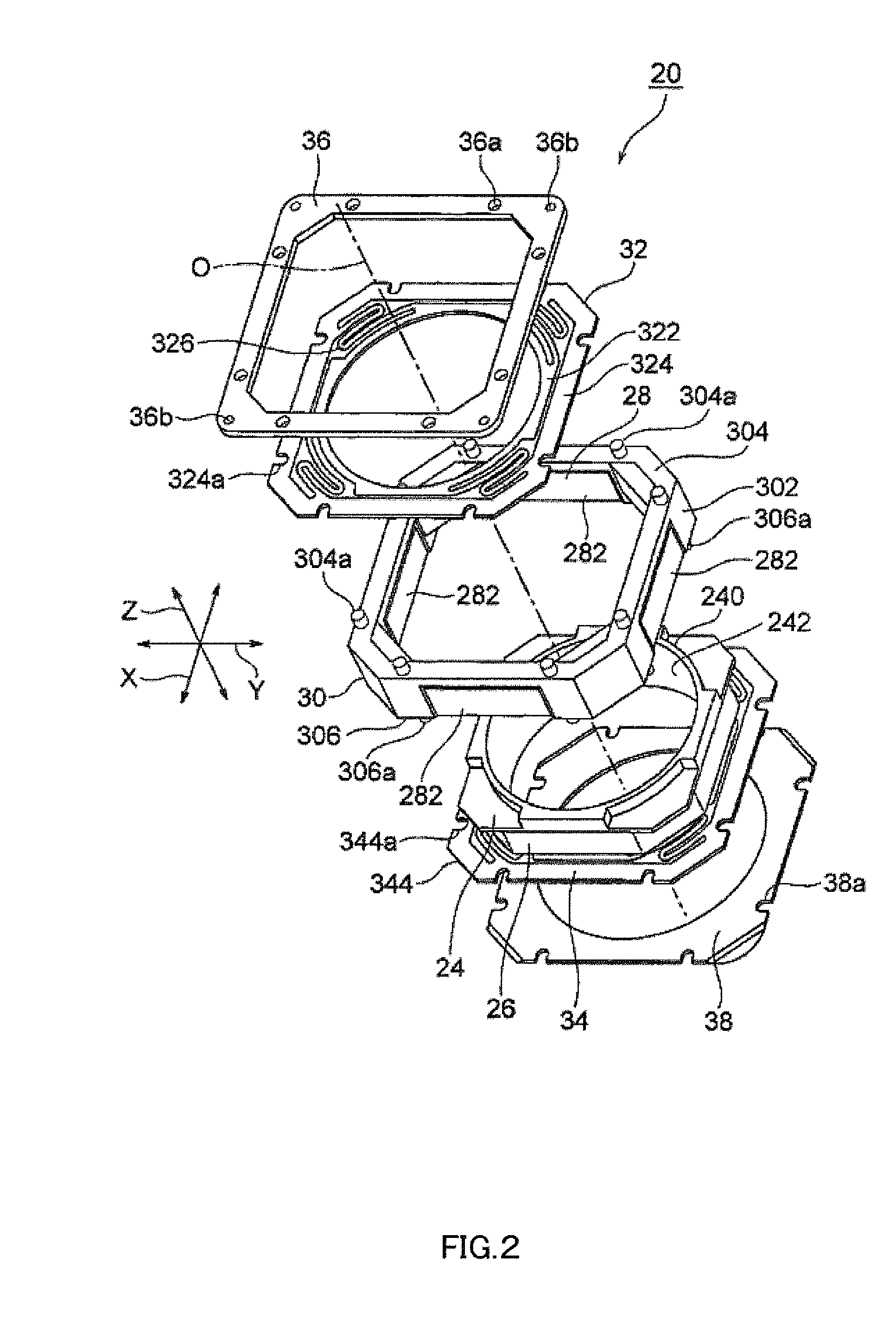
[0091]Camera-shake correction apparatus (lens holder drive apparatus) 10 according to the present invention will now be described with reference to FIG. 1 through FIG. 3. FIG. 1 is an exploded oblique view of camera-shake correction apparatus 10. FIG. 2 is an exploded oblique view of auto-focusing lens drive apparatus 20 used in camera-shake correction apparatus 10 shown in FIG. 1. FIG. 3 is an assembled oblique view, excluding shield cover 42, of camera-shake correction apparatus 10 shown in FIG. 1.

[0092]Here, orthogonal coordinate system (X,Y,Z) is used, as shown in FIG. 1 through FIG. 3. In the states illustrated in FIG. 1 through FIG. 3, in orthogonal coordinate system (X,Y,Z), the X-axis direction is the front-back direction (depth direction), the Y-axis direction is the horizontal direction (width direction), and the Z-axis direction is the vertical-direction (height direction). In the examples shown in FIG. 1 through FIG. 3, vertical direction Z is the lens optical axis O dir...

second embodiment

[0140]Camera-shake correction apparatus (lens holder drive apparatus) 10A according to the present invention will now be described with reference to FIG. 5 through FIG. 8. FIG. 5 is an external oblique view of camera-shake correction apparatus 10A. FIG. 6 is a vertical cross-sectional view of camera-shake correction apparatus 10A. FIG. 7 is an exploded oblique view of camera-shake correction apparatus 10A. FIG. 8 is an exploded oblique view of auto-focusing lens drive apparatus 20A used in camera-shake correction apparatus 10A shown in FIG. 5.

[0141]Here, orthogonal coordinate system (X,Y,Z) is used, as shown in FIG. 5 through FIG. 8. In the states illustrated in FIG. 5 through FIG. 8, in orthogonal coordinate system (X,Y,Z), the X-axis direction is the front-back direction (depth direction), the Y-axis direction is the horizontal direction (width direction), and the Z-axis direction is the vertical-direction (height direction). In the examples shown in FIG. 5 through FIG. 8, vertica...

third embodiment

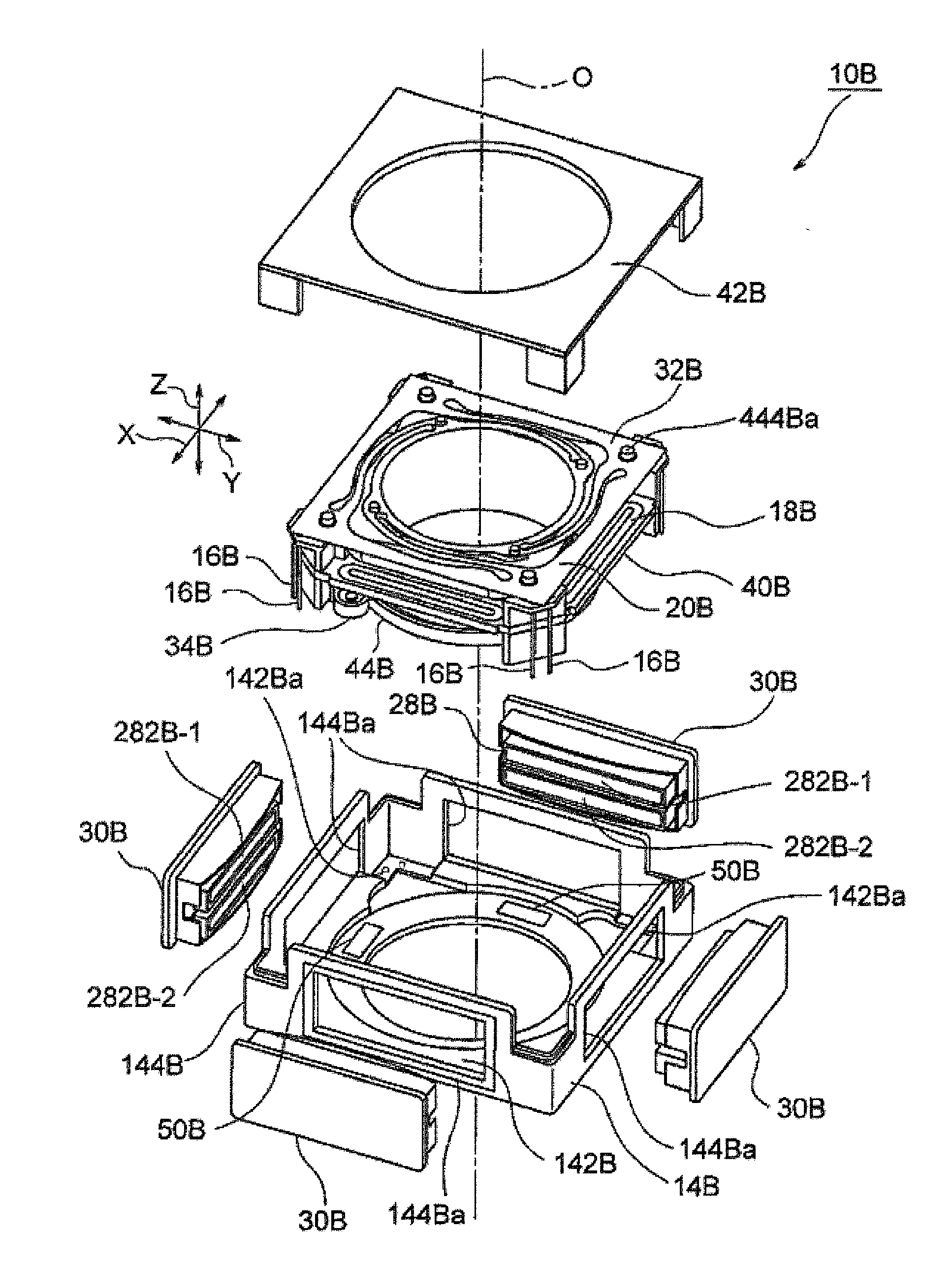
[0202]Camera-shake correction apparatus (lens holder drive apparatus) 10B according to the present invention will now be described with reference to FIG. 12 through FIG. 15. FIG. 12 is an external oblique view of camera-shake correction apparatus 10B. FIG. 13 is a vertical cross-sectional view of camera-shake correction apparatus 10B. FIG. 14 is an exploded oblique view of camera-shake correction apparatus 10B. FIG. 15 is an exploded oblique view of auto-focusing lens drive apparatus 20B used in camera-shake correction apparatus 10B shown in FIG. 12.

[0203]Here, orthogonal coordinate system (X,Y,Z) is used, as shown in FIG. 12 through FIG. 15. In the states illustrated in FIG. 12 through FIG. 15, in orthogonal coordinate system (X,Y,Z), the X-axis direction is the front-back direction (depth direction), the Y-axis direction is the horizontal direction (width direction), and the Z-axis direction is the vertical-direction (height direction). In the examples shown in FIG. 12 through FIG...


PUM


Abstract

Provided is a small, low-profile lens holder apparatus. A lens holder apparatus includes: a lens holder to which a lens section can be attached; a first drive section that moves the lens holder in a first direction along the optical axis; a second drive section that moves the lens holder in a second direction and / or third direction that are perpendicular to the optical axis and differ from each other; a supporting section that includes a base disposed in a position spaced from the lens holder and a supporting member that supports the lens holder so as to be able to move in the second direction and / or third direction; and a position detection section that is disposed on the supporting section in order to detect a position in the second direction and / or third direction of the lens holder with respect to the base.

Description

CROSS REFERENCE TO RELATED APPLICATIONS[0001]This application is a continuation-in-part of U.S. patent application Ser. No. 13 / 390,603, filed on Feb. 15, 2012, which is National Stage Application of International Application No. PCT / JP2010 / 063683, filed Aug. 12, 2000, the disclosure of which is incorporated herein by reference in its entirety.[0002]International Application No. PCT / JP2010 / 063683 is entitled to and claims the benefit of Japanese Patent Application No. 2009-191619, filed on Aug. 21, 2009, and Japanese Patent Application No. 2010-158602, filed on Jul. 13, 2010, the disclosures of which are incorporated herein by reference in their entirety.TECHNICAL FIELD[0003]The present invention relates to a lens holder drive apparatus and a camera equipped therewith, and more particularly to a lens holder drive apparatus and a camera equipped therewith that correct camera shake (vibration) that occurs when a still image is captured with a small camera for mobile phone use, and enab...

Claims


Application Information

Patent Timeline
Patent Type & Authority Applications(United States)
IPC IPC(8): G02B27/64
CPCG02B27/646G02B7/08G03B3/10G03B5/00G02B7/09G03B5/06G03B13/36G03B2205/0015G03B2205/0069H04N23/57H04N23/55H04N23/68H04N23/685H04N23/687H04N23/54H04N23/682H04N25/00G03B3/00G03B17/02G03B17/00G02B13/001
Inventor MORIYA, AKIHIROSUGAWARA, MASAYOSHI
Owner MITSUMI ELECTRIC CO LTD
Why Eureka
Try Eureka