
Vehicle door trim panel and method for manufacturing the same

a technology for vehicle door trim and door trim, which is applied in the direction of vehicular safety arrangments, pedestrian/occupant safety arrangements, and cellulosic plastic layered products, etc., can solve the problems of low cost and only a small amount of weight increase of vehicle door trim panels, and achieve the effect of reducing the possibility

Inactive Publication Date: 2012-09-13
HAYASHI GIJUTSU KENKYUSHO KK
View PDF2 Cites 13 Cited by
  • Summary
  • Abstract
  • Description
  • Claims
  • Application Information

AI Technical Summary

Benefits of technology

[0010]The present invention aims at providing a light weight and low-cost vehicle door trim panel in which there is reduced possibility for cracks and sharp edges to occur in the resin core when an impact load is applied to the side surface of the vehicle, and also aims at providing a method for manufacturing such a vehicle door trim panel.
[0012]Cracks of the resin core are generated at the outer edge of the resin core or at the peripheral edge of an aperture, if such an aperture is present, and propagate from the crack initiating point. The force applied to the outer edge or the peripheral edge is considered to be of the type that tears the resin core along the outer edge or the peripheral edge. In the present invention, the tape member is applied along the outer edge or the peripheral edge, i.e., applied in the same direction as the tearing force, and hence it is possible to effectively prevent the generation and propagation of cracks. Therefore, it is also possible to prevent the generation of sharp edges caused by the cracks. In addition, the vehicle door trim panel has only a small amount of weight increase and is low-cost because the tape member is used for reinforcement.
[0013]According to the present invention, it is possible to provide a light weight and low-cost vehicle door trim panel in which there is reduced possibility for cracks and sharp edges to occur in the resin core when an impact load is applied to the side surface of the vehicle, and also to provide a method for manufacturing the vehicle door trim panel.

Problems solved by technology

In addition, the vehicle door trim panel has only a small amount of weight increase and is low-cost because the tape member is used for reinforcement.

Method used


Image

  • Vehicle door trim panel and method for manufacturing the same
  • Vehicle door trim panel and method for manufacturing the same
  • Vehicle door trim panel and method for manufacturing the same

Examples


Embodiment Construction

[0022]Referring to the drawings, embodiments of the vehicle door trim panel of the present invention will be described below.

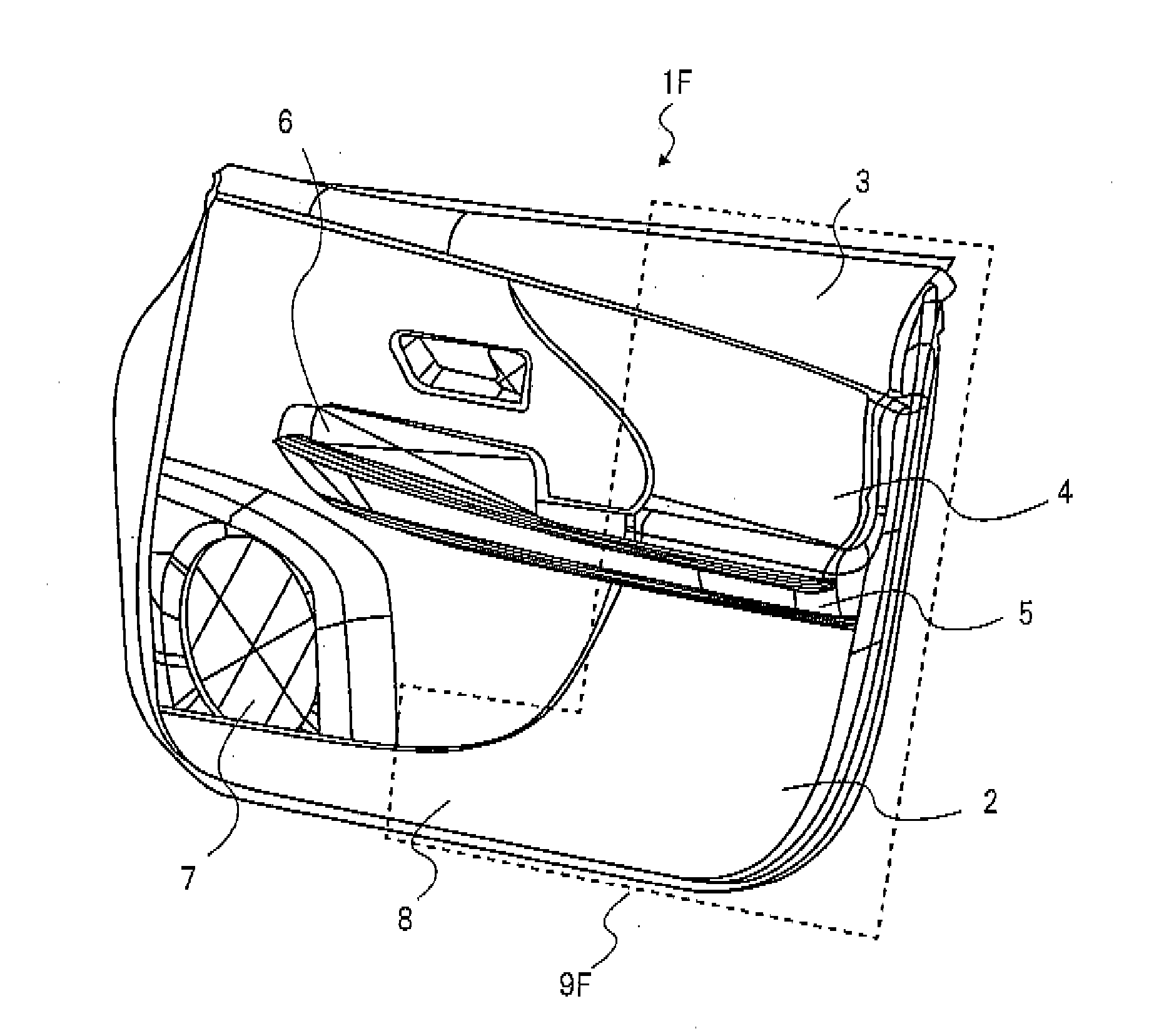
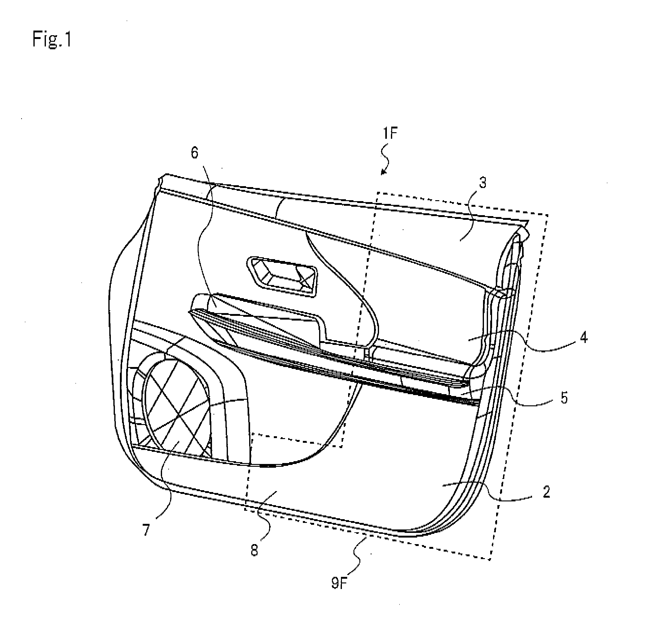
[0023]FIG. 1 is a general schematic view of the front door trim panel according to an embodiment of the present invention, as viewed from the vehicle compartment. FIG. 1 shows an example of the front door trim panel. Front door trim panel 1F according to the embodiment is generally composed of three separate parts, i.e., trim lower member 2, trim upper member 3 and ornament 4. The vehicle door trim panel of the present invention is not limited to a structure of three separate parts, but may be formed as a one-piece structure or as a two-piece structure. These members are formed in desired curved shapes and are attached to the door inner panel (not shown) from the compartment side by means of mounting means, such as clips (not shown). Arm rest 5, pull handle 6, speaker grill 7, door pocket 8 etc. are formed on trim lower member 2 which occupies the greater port...


PUM

PropertyMeasurementUnit
thicknessaaaaaaaaaa
melt indexaaaaaaaaaa
weightaaaaaaaaaa

Abstract

A vehicle door trim panel has a resin core. The resin core has a foam layer and a skin layer that covers the foam layer. The skin layer is harder and thinner than the foam layer. A tape member is applied to the resin core along at least a part of an outer edge of the resin core or along at least a part of a peripheral edge of an aperture of the resin core.

Description

[0001]The present application is based on, and claims priority from, JP Application No. 2011-53008, filed on Mar. 10, 2011, the disclosure of which is hereby incorporated by reference herein in its entirety.BACKGROUND OF THE INVENTION[0002]1. Field of the Invention[0003]The present invention relates to a vehicle door trim panel which is mounted on a door panel of a vehicle from inside the vehicle. The present invention also relates to a method for manufacturing the vehicle door trim panel.[0004]2. Description of the Related Art[0005]A vehicle door trim panel which is mounted on a door panel from inside the vehicle provides various functions for passengers and gives ornamental features to the vehicle compartment. Side impact loads are mainly absorbed by the door panel and in order to prevent injuries to passengers, a need has developed for a vehicle door trim panel in which there will be no occurrence of cracks or sharp edges, that are caused by cracking, on the interior surface of t...

Claims


Application Information

Patent Timeline
Patent Type & Authority Applications(United States)
IPC IPC(8): B60R13/02B32B3/02B32B3/24B29C71/00
CPCB60R13/0243Y10T428/24777B32B5/18B32B25/045B32B25/16B32B27/065B32B27/302B32B27/32B32B27/34B32B27/36B32B2266/0228B32B2266/025B32B2266/0257B32B2266/0264B32B2266/0271B32B2605/08Y10T428/24331B60R21/0428
Inventor HAYASHI, KEN-ICHI
Owner HAYASHI GIJUTSU KENKYUSHO KK
Learn More