Medical implanatble lead with fixation detection

a technology of fixation and implanatble leads, which is applied in the field of medical implanatble leads with fixation detection, can solve the problems of poor helix fixation, difficult to verify the performance of the attachment, and no good way to verify whether a helix is properly secured to the tissue, so as to prevent too deep penetration into the tissue

Active Publication Date: 2012-09-13
ST JUDE MEDICAL
View PDF3 Cites 23 Cited by
  • Summary
  • Abstract
  • Description
  • Claims
  • Application Information

AI Technical Summary

Benefits of technology

[0012]In a still further embodiment, the lead is provided with a continuous through bore from the proximal to the distal end, i.e. also through the shaft, such that a temporary conductor in form of a stylet is ensertable through the bore for contact with or penetration into the tissue. Accordingly, in this embodiment the stylet will function not only as a conductor, but also its distal end will function as the second contact surface and its proximal end will function as a connector to be connected to a measuring device. In order to prevent too deep penetration into the tissue, the stylet should be provided with some kind of stop member, which can engage with a mating stop member of the lead. In the hereinafter illustrated and described embodiment, the stop member on the stylet is in form of a shoulder portion near its distal end which engages a corresponding shoulder portion inside the bore. However, the stop members could be formed in many different ways, e.g. as a pin on the stylet, and be positioned also at other locations, e.g. in its proximal end. To prevent electric contact with conductors within the bore or with the shaft, the stylet could be provided with an electrically insulating layer except in its distal end, which is adapted to function as the second contact surface, and in its proximal end, which is adapted to function as a connector. The stylet could preferably be formed of or comprise a radiopaque material to visually be able to determine whether it is correct positioned or not.
[0013]It is to be understood that the electric measuring of whether the second contact surface is electric contact with the tissue or not, can be carried out in different ways and by means of different equipment. In case of a medical implantable lead connected to a heart, it is possible to use a so called Pacing System Analyzer (PSA) and via the second contact surface detect a sufficient R-wave amplitude which would indicate a proper contact with the tissue. Using the PSA it is also possible to send out pace pulses that would enter the heart muscle via the second contact surface and a proper voltage capture level will indicate a secure helix engagement to the heart tissue. When using a penetrating member, such as a pin or a stylet, as a second contact surface, it would also be possible to detect a current of injury signal from the injured cells in the tissue, which would indicate a proper attached helix.

Problems solved by technology

The physician performing the implantation cannot actually see when the implantation is performed other than by means of x-ray imaging and accordingly it is hard to verify the performance of the attachment.
Poor helix fixation is a well known problem and till now there has been no good way of verifying whether a helix is properly secured to the tissue or not.
Both of these methods are associated with drawbacks since they can appear to indicate a proper fixation even when only a small part of the helix actually is secured to the tissue.
However, by this method it is not possible to see whether these wire loops are embedded into tissue or not, since the tissue itself is not visible on the images.
This result in a risk that the helix my become completely screwed out while the physician continuous to rotate the helix rotating control member such that the distal end of the whole lead is twisted and may perforate e.g. a heart wall.

Method used


Image

  • Medical implanatble lead with fixation detection
  • Medical implanatble lead with fixation detection
  • Medical implanatble lead with fixation detection

Examples


first embodiment

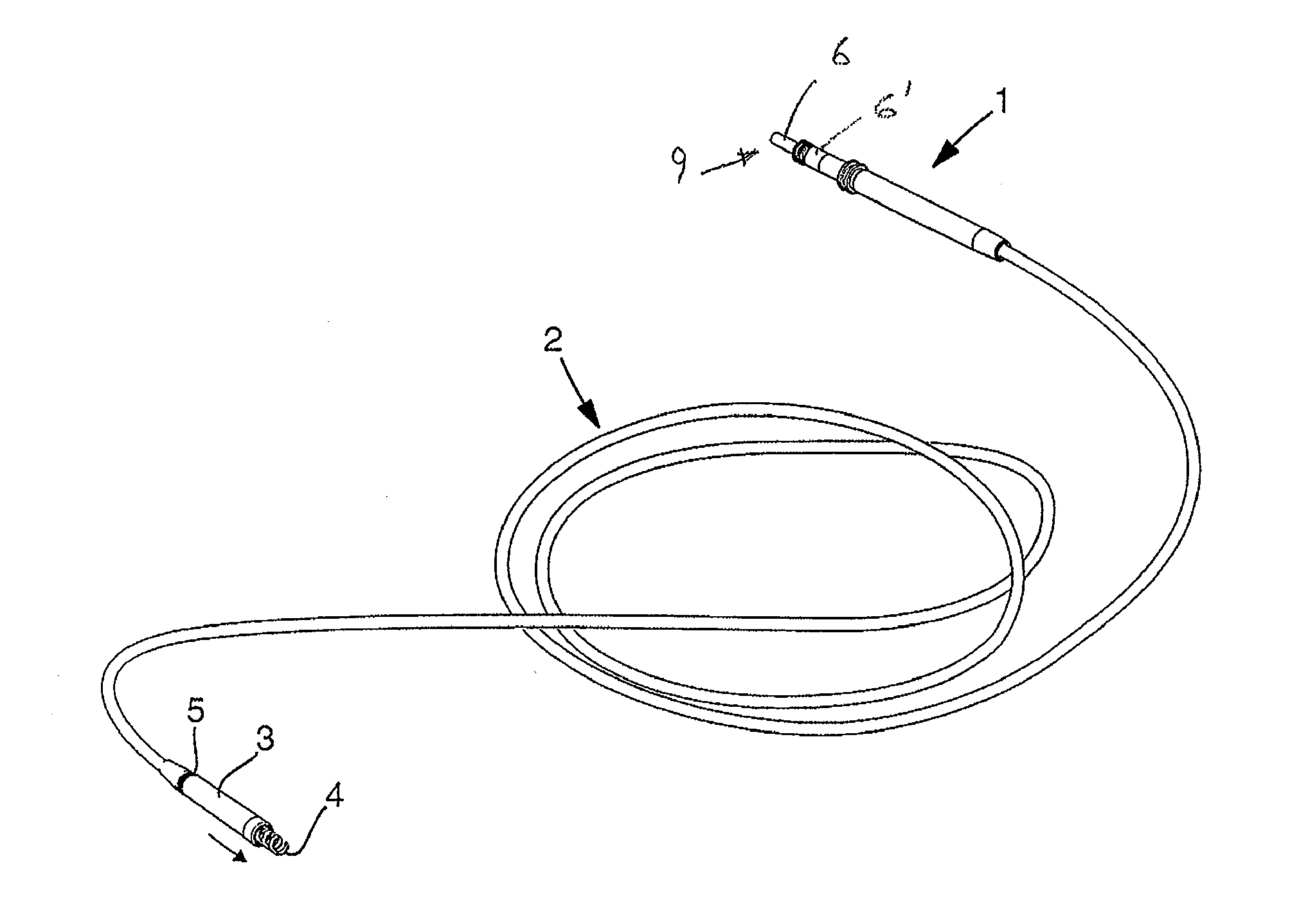
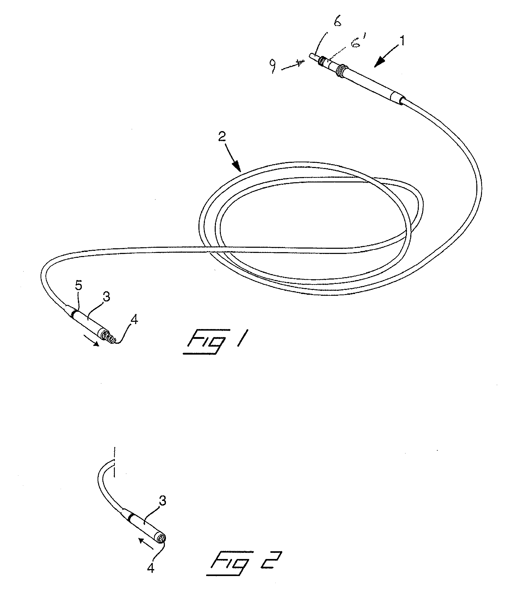
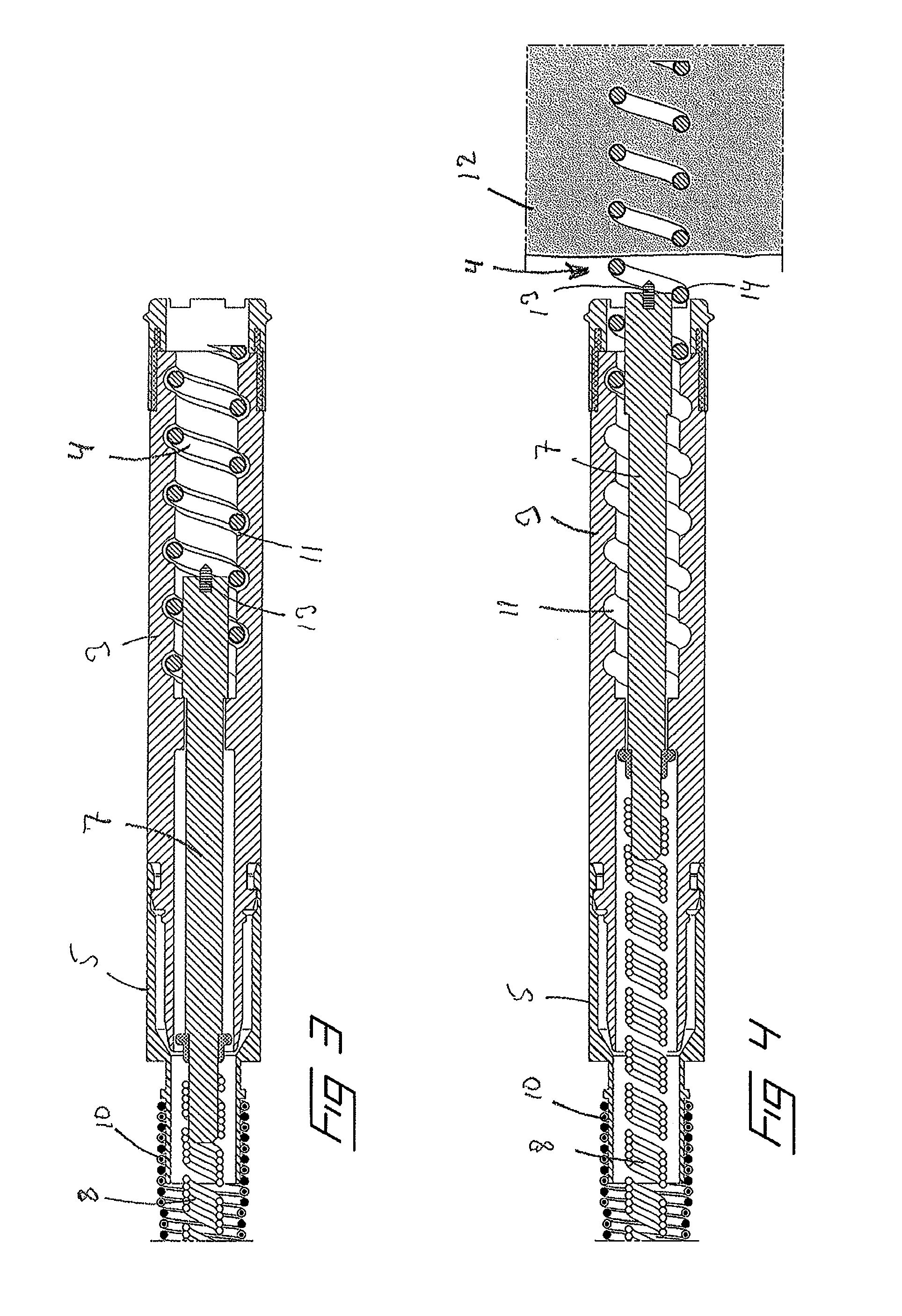
[0031]Next, reference is made to FIGS. 3-6, in which is illustrated the invention in longitudinal sections, in FIGS. 3-5, through the distal end of the lead and in a perspective view in FIG. 6. As is commonly known in the art, the helix 4 is attached to an electrically conducting shaft 7, which is rotatable and displaceable within the header 3. In a proximal end, the shaft 7 is connected to a torque transferring member, which in the illustrated embodiment also function as conductor since it is formed as a wire coil 8 composed of at least one electrically conducting wire and can be rotated by rotating a control pin 9 (FIG. 1) in the proximal end of the lead. The wire coil 8 connects the helix to the first connector 6 on the control pin 9. In addition to the inner wire coil 8, the lead also comprises a second, outer wire coil 10, which connects the indifferent electrode 5 to the second connector 6′. The helix is journalled in a helicoidal groove 11 on the inside of the header. Accordi...

second embodiment

[0033]In FIG. 7 is disclosed the invention which is similar to the embodiment according to FIGS. 3-6. However, in this embodiment the shaft 7 is not provided with a pin. Instead the distal end of the shaft is formed with a planar contact surface 15 which, when the helix is correct mounted, will abut against and make electric contact with the surface of the tissue, which is detectable by means of an electric measuring device. As in the embodiment according to FIGS. 3-6, the helix is coated by an electrically insulating layer 14 of a biologically dissolvable material.

[0034]FIG. 8 illustrates a third embodiment by which the shaft is not provided with an auxiliary contact surface, like the pin and the planar contact surface of the first and second embodiments according to FIGS. 3-6 and 7, respectively. Like these embodiments, the helix 4 is coated with an electrically insulating layer 14 of a biologically dissolvable material. However, in this embodiment only a distal portion of the hel...

fourth embodiment

[0035]the invention is illustrated in FIG. 9. Here, the helix has no electrically insulating layer of a biologically dissolvable material, as in the previous embodiments. Instead, the shaft 7 is provided with a pin 13 in its distal end which is electrically insulated from the shaft. A separate insulated conductor 17 is arranged in a central passage in the longitudinal direction of the shaft between the pin and an electrically controlled switch 18 in the proximal end of the haft. The switch 18 can for example be arranged as any of the switches in U.S. Pat. No. 5,423,873 or US 2008 / 0294218. By arranging a switch of this kind it is possible to have one conductor, the inner wire coil 8 between the proximal end of the lead and the switch, and by control signals control the switch to connect either to the pin 13 or to the helix 4. By switching to the pin during implantation it is possible to measure if the lead is correctly mounted, in which case there will be an electric contact between ...


PUM


Abstract

The invention relates to a medical implantable lead of the kind being adapted to be implanted into a human or animal body for monitoring and/or controlling of an organ inside the body. The lead comprises in a distal end a tubular header (3) inside which a shaft (7) is rotatable as well as extendable and retractable arranged and carries in a distal end a combined fixation means and electrode member in form of a helix (4), which is provided with a first contact surface being electrically connectible to a connector at the proximal end of the lead by means of an electric conductor (8), and which by means of the shaft is rotatable in relation to the lead and extendable out from the distal end to be able to fixate the distal end of the lead to the organ by being screwed into the tissue. The shaft also carries a second contact surface (13) being positioned on or adjacent a proximal portion of the helix and being connectible to a connector at the proximal end of the lead by means of an electric conductor (8). The lead comprises a conduction controlling means (14), which at least during an initial stage after implantation is capable of render the first contact surface electrically inactive and which is capable of render the first contact surface electrically active after the initial stage. By means of the inventive lead it is possible to detect whether the helix is sufficient screwed into the tissue (12) or not.

Description

[0001]The present invention relates to a medical implantable lead of the kind being adapted to be implanted into a human or animal body for monitoring and / or controlling of an organ inside the body, comprising in a distal end a tubular header inside which a shaft is rotatable as well as extendable and retractable arranged and carries in a distal end a combined fixation means and electrode member in form of a helix, which is provided with a first contact surface being electrically connectible to a connector at the proximal end of the lead by means of an electric conductor, and which by means of the shaft is rotatable in relation to the lead and extendable out from the distal end to be able to fixate the distal end of the lead to the organ by being screwed into the tissue, wherein the shaft also is provided with a second contact surface being positioned on or adjacent a proximal portion of the helix which is located beyond the distal end of the shaft and being connectible to a connect...

Claims


Application Information

Patent Timeline
Patent Type & Authority Applications(United States)
IPC IPC(8): A61N1/05A61B5/04
CPCA61N1/0573A61B5/6869A61B5/686A61N1/05A61B5/04A61B5/6882A61B5/24
Inventor HALLANDER, SARAHELGESSON, MARCUS
Owner ST JUDE MEDICAL
Why Eureka
Try Eureka