

Systems and methods to compensate for compression forces in an intravascular device
a compression force and intravascular technology, applied in the field of systems and methods to compensate for compression forces in intravascular devices, can solve the problem of reducing the ability of clinicians to confirm proper catheter placement, and achieve the effect of increasing the surface area of the distal opening
- Summary
- Abstract
- Description
- Claims
- Application Information
AI Technical Summary
Benefits of technology
Problems solved by technology
Method used
Image

Examples
Embodiment Construction
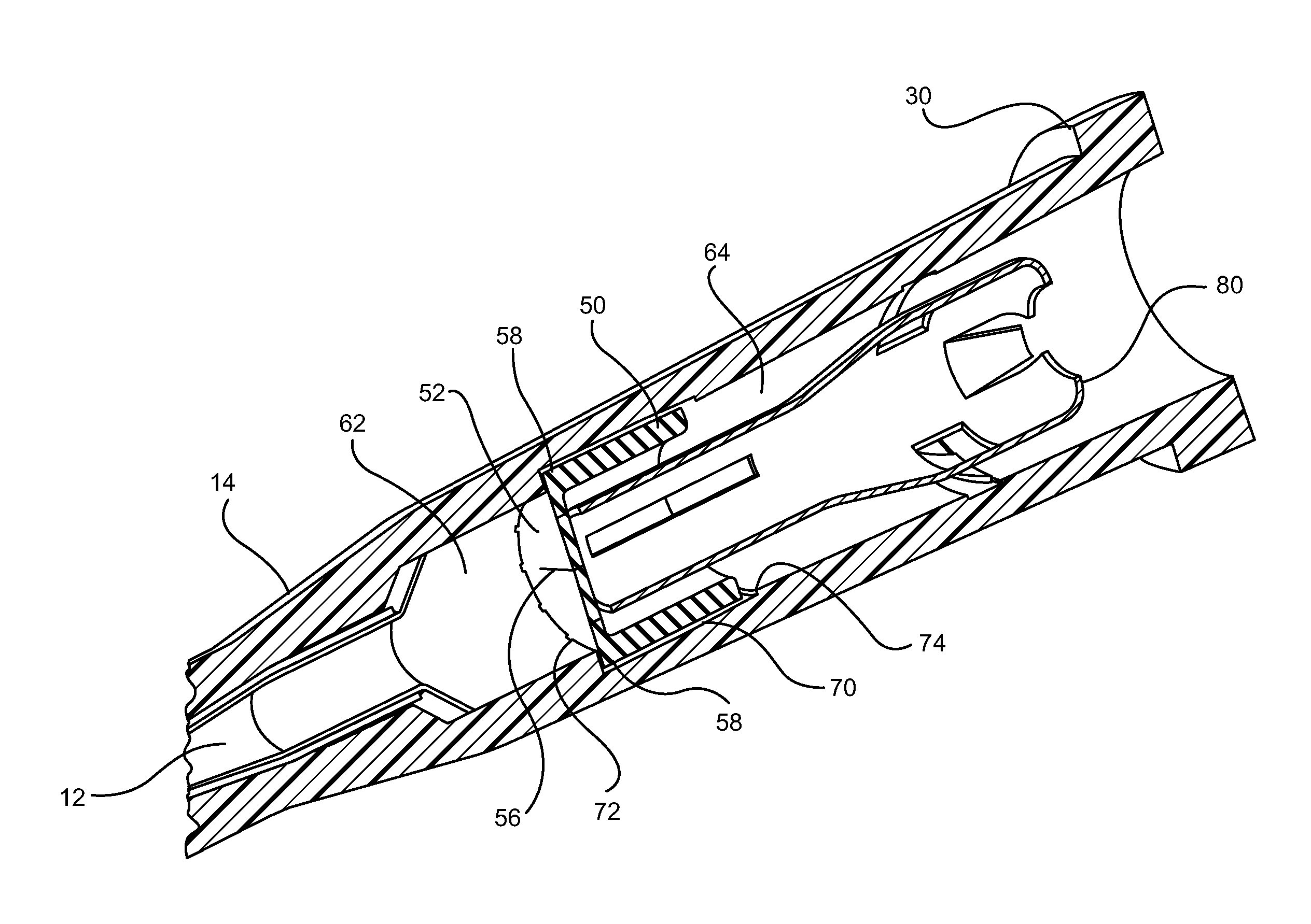
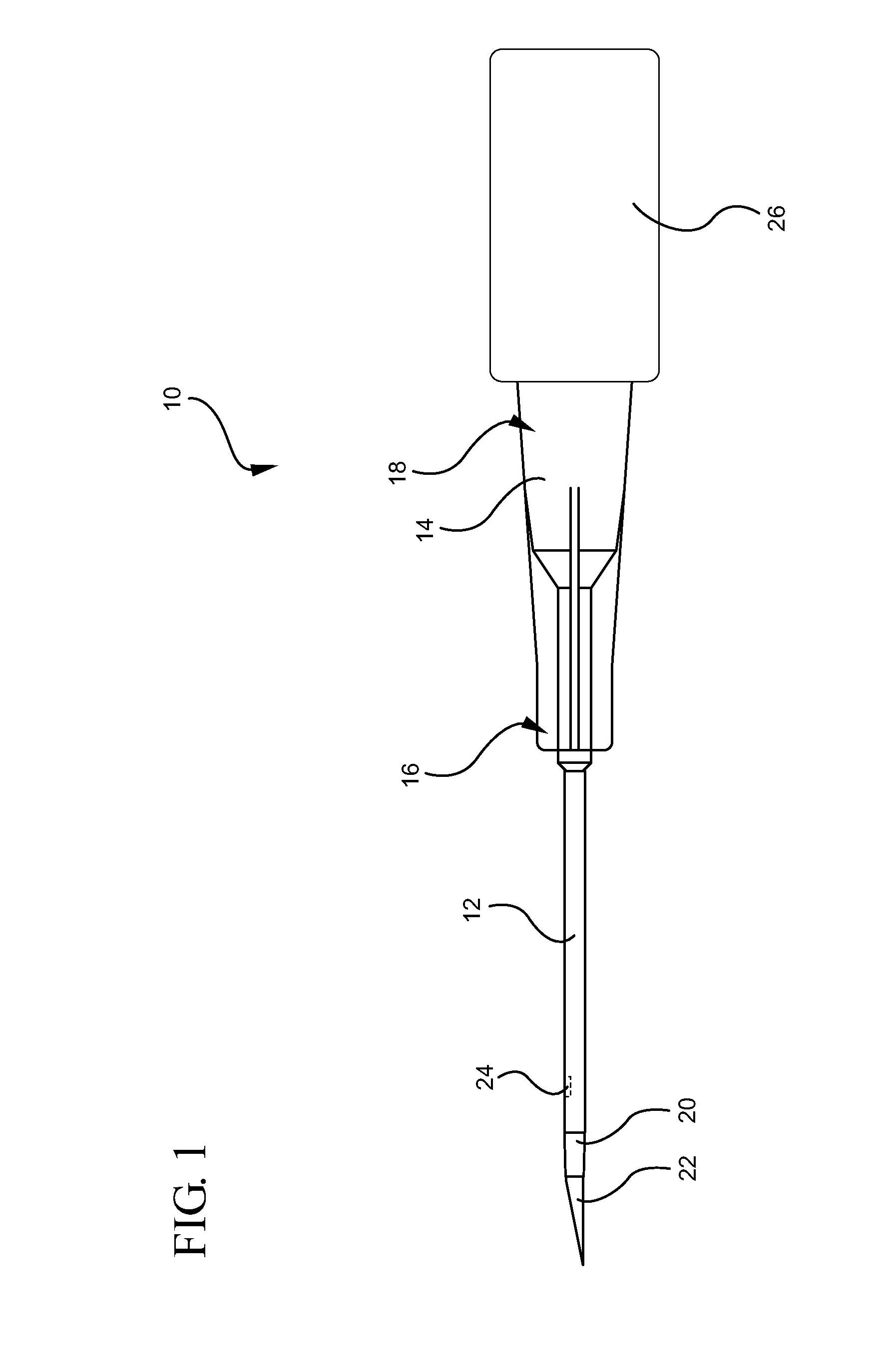
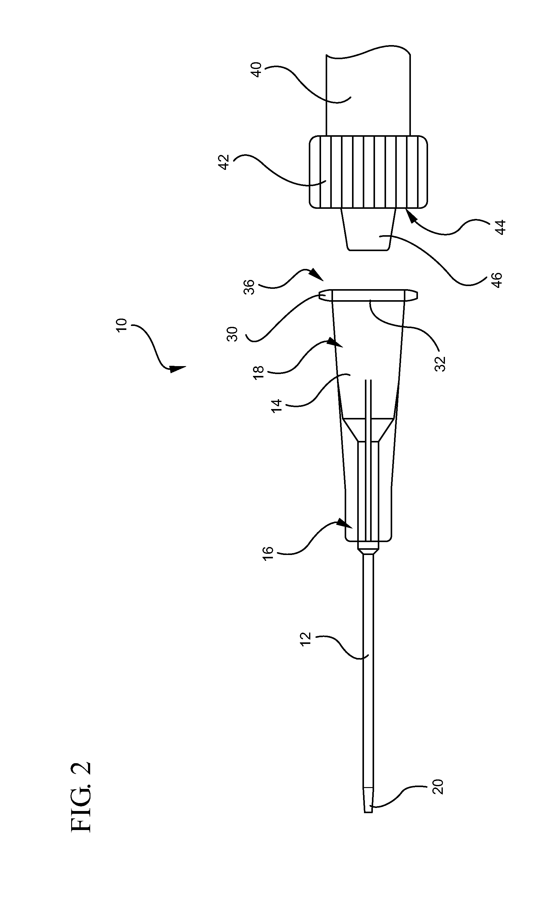
[0024]Referring now to FIG. 1, an intravascular device 10 is illustrated. The intravascular device 10 generally includes a catheter 12 coupled to a distal end 16 of a catheter adapter 14. The catheter 12 and the catheter adapter 14 are integrally coupled such that an inner lumen of the catheter adapter 14 is in fluid communication with an inner lumen of the catheter 12. The catheter 12 generally comprises a biocompatible material having sufficient rigidity to withstand pressures associated with insertion of the catheter into a patient.
[0025]In some embodiments, as shown, the catheter 12 is an over-the-needle catheter that is made of a flexible or semi-flexible polymer material and which may be used in combination with a rigid introducer needle 22. The rigid introducer needle 22 enables the insertion of the non-rigid over-the-needle catheter into a patient. The introducer needle 22 can be coupled to a needle hub 26 that is selectively coupled to the proximal end 18 of the catheter ad...
PUM
 Abstract
Description
Claims
Application Information