Non-contact torque measurement apparatus and methd

Inactive Publication Date: 2012-09-20
HALLIBURTON ENERGY SERVICES INC
View PDF27 Cites 36 Cited by
  • Summary
  • Abstract
  • Description
  • Claims
  • Application Information

AI Technical Summary

Benefits of technology

[0018]According to the apparatus and methods of one embodiment of the present invention, torque in a shaft can be measured accurately under difficult conditions using a magnetic-detector configuration. Permanent magnets placed along the shaft induce current or

Problems solved by technology

Two fluids are incompatible if undesirable physical or chemical interactions occur when the fluids are mixed.
Incompatibility is characterized by undesirable changes in apparent viscosi

Method used


Image

  • Non-contact torque measurement apparatus and methd
  • Non-contact torque measurement apparatus and methd
  • Non-contact torque measurement apparatus and methd

Examples


Example

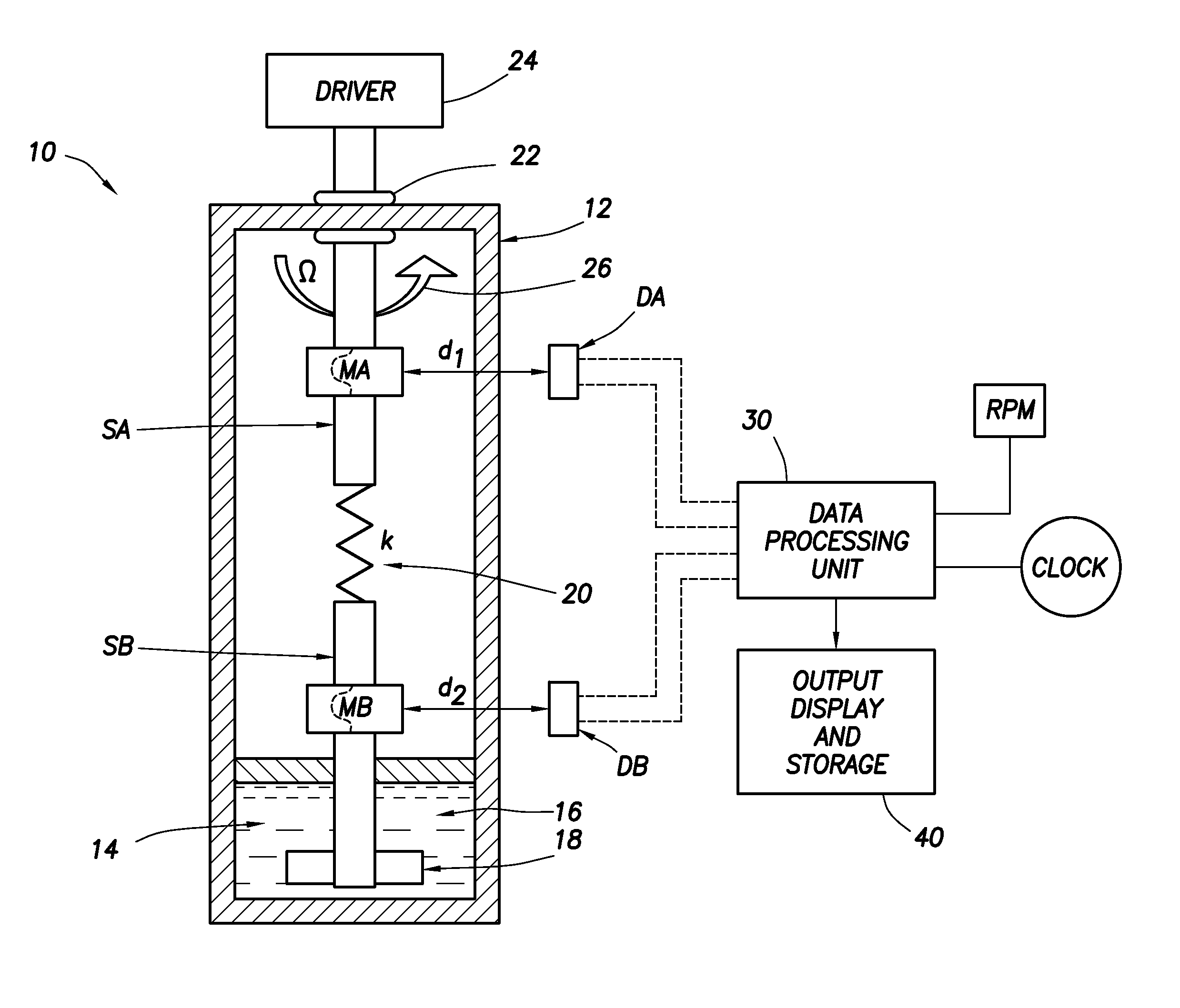
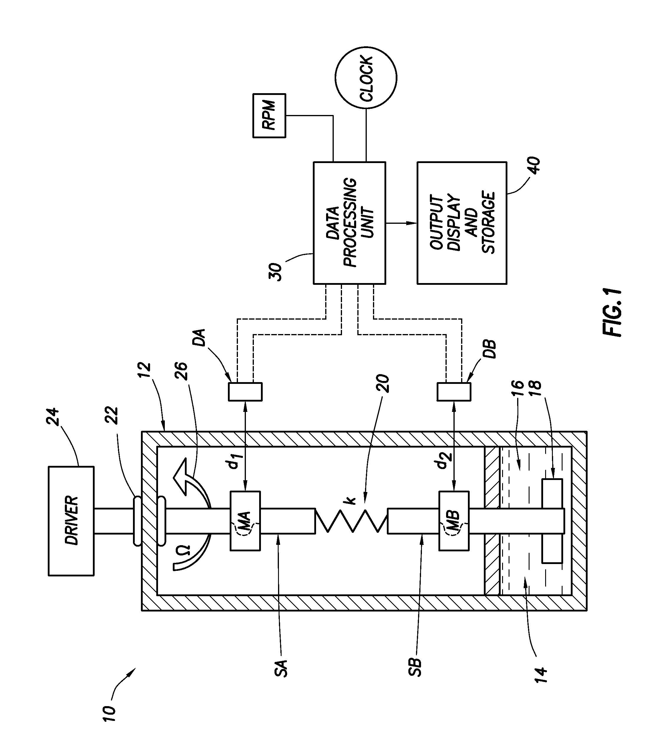
[0023]Referring now to the drawings, wherein like or corresponding parts are designated by like or corresponding reference numbers throughout the several views, there is schematically illustrated in FIG. 1, a fluid testing apparatus 10 embodying the method and apparatus of the present inventions. The apparatus 10 comprises a housing 12, enclosing a test chamber 14 containing the fluid 16 to be tested. The space in the housing 12 above the test chamber can be filled with an inert fluid. In the preferred embodiment, the housing and the test chamber are sealed enclosures that can be raised in pressure to perform tests on the fluid in the chamber 14. A shaft formed by two shaft segments SA and SB extends into housing 12. According to the present inventions, a paddle 18 mounted on shaft SB is rotated in the test chamber 14 while in contact with the test fluid 16 to measure the apparent viscosity of the test fluid.

[0024]In one embodiment, a resilient member embodied as a torsion spring 22...


PUM


Abstract

Disclosed is an apparatus and method for accurately measuring torque in a rotating shaft. The apparatus comprises axially spaced magnet-detector pairs, mounted to rotate with the shaft and means for sensing relative rotation between the magnets.

Description

CROSS REFERENCE TO RELATED APPLICATIONS[0001]This application is a continuation-in-part of U.S. application Ser. No. 12,869,447, filed on Aug. 26, 2010.BACKGROUND[0002]1. Technical Field[0003]This invention relates, generally, to apparatus and methods used in measuring torque in a shaft. In particular, this invention relates to non-contact torsion measurement on a rotating shaft assembly, comprising two rigid shafts segments connected by a flexible torsion member.[0004]This invention relates to torque measurement in the following conditions while not compromising on performance and accuracy:[0005]1) Harsh environments, High Pressure, High Temperature;[0006]2) Presence of Corrosive, Particle Laden and Non-Clear (dirty) fluids;[0007]3) High Rotating Speeds;[0008]4) Wide Span of Torque Ranges over several orders of magnitude;[0009]5) End of Shaft not accessible;[0010]6) Large Offset Distances between Shaft and Sensing elements; and[0011]7) Vibration and Noise.[0012]In one embodiment, t...

Claims


Application Information

Patent Timeline
IPC IPC(8): G01L3/10
CPCG01N2011/0086G01N11/14
Inventor PINDIPROLU, SAIRAM KSSHAH, VIMAL V.GAO, LI
Owner HALLIBURTON ENERGY SERVICES INC
Why Eureka
Try Eureka