Surgical, therapeutic, or diagnostic tool

a technology of diagnostic tools and soft tissue, applied in the field of surgical, therapeutic or diagnostic tools, can solve the problems of inability to accurately support on the soft tissue in the neighbourhood where a resection, a biopsy or another surgical act needs to be performed, and the current generation of soft tissue guides cannot be used, so as to achieve rapid prototyping and eliminate the degree of freedom

Inactive Publication Date: 2012-09-20
MATERIALISE NV
View PDF1 Cites 9 Cited by
  • Summary
  • Abstract
  • Description
  • Claims
  • Application Information

AI Technical Summary

Benefits of technology

[0059]It is the conscious use of clamping designed to fit on surface areas of the skin where underlying rigidity can be accessed to limit certain degrees of freedom in the total guide device movement that discriminate the current invention from manually pressed or screwed soft tissue guides in the prior art. When the guide device extends over articulating body parts (joints), the positional clamping can be used to fix the articulations in a defined position by their mechanism to eliminate degrees of freedom.
[0060]The method may include making the guide by any additive manufacturing route such as layered manufacturing, e.g. a rapid prototyping process.

Problems solved by technology

However, this technique is limited to areas in which the contact surface provides adequate fixation for unique positioning of the device and which have a fixed position relative to the underlying anatomy.
Unfortunately there are situations, for instance for the placement of intercalary femur implants, where the current generation of soft tissue guides can not be used.
The muscle tissue in those regions is so thick that supporting on the soft tissue in the neighbourhood where a resection or a biopsy or another surgical act needs to be performed accurately is impossible.
Even a quite large soft tissue guide that is placed on a considerable area of the tight muscles does not feel stable after placement.
The situation can be further complicated when attempting to guide over a joint, e.g. knee or elbow, since it introduces additional degrees of freedom between the fitting surfaces.
Unique positioning will often be a problem on these regions, especially with obese patients.
The result is that multiple surgical acts in those regions are difficult to perform in a guided way and therefore rely on the surgeon's mental and visual navigation.
This can be problematic for the same reasons as those that affect the fit of mechanical guides, but also due to the fact that the position of the body of the patient may be quite different on the operation table as during the time that the scans were taken.
While this approach manages to restrict the position of a soft tissue region to a known position, the initial brace does not fit onto a predefined patient specific position, and relies on the technologies inherent to electronic surgical navigation to relate its position to the patient's anatomy.
Due to its lack of unique positioning, the brace also cannot be used during imaging to relate its position to the patient's anatomy for pre-operative planning.
In this sense, it suffers from the same limitations as electronic navigation as described above.
Unfortunately, this approach is expensive and has a large number of potential problems or inconveniences that need to be taken into account.
For example, most 3D-image scanners leave insufficient room for the surgeon to operate.
In addition, both the patient and the clinicians can be exposed to excessive radiation.
In general when this approach is used it is mostly done with 2D X-ray imaging which gives only partial positioning information and still has the drawback of emitting radiation.
While the currently existing devices can help position the surgeon's instrumentation, most of these current methods do not allow for pre-operative planning which can be directly transferred to the surgical theatre.
Some navigation systems allow pre-operative plans to be imported and followed intra-operatively, however, its accuracy is still limited by anatomic marker place and image registration as stated previously.
The creation of form fitting guides allows for a direct transfer of the pre-operative plan to the patient but this technology is limited by the quality of the guide's fit.

Method used


Image

  • Surgical, therapeutic, or diagnostic tool
  • Surgical, therapeutic, or diagnostic tool
  • Surgical, therapeutic, or diagnostic tool

Examples


Embodiment Construction

[0067]The present invention will be described with respect to particular embodiments and with reference to certain drawings but the invention is not limited thereto but only by the claims. The drawings described are only schematic and are non-limiting.

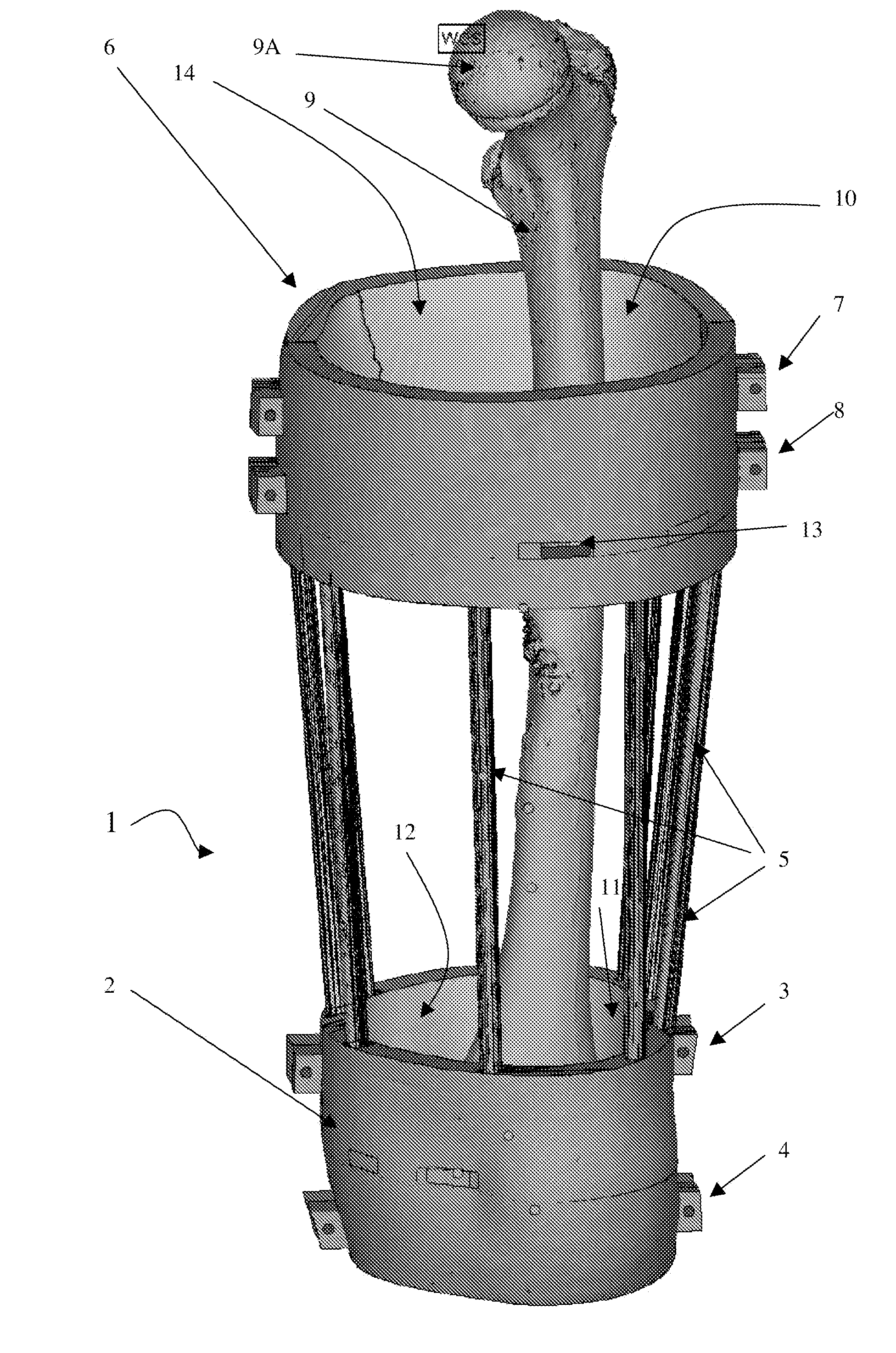
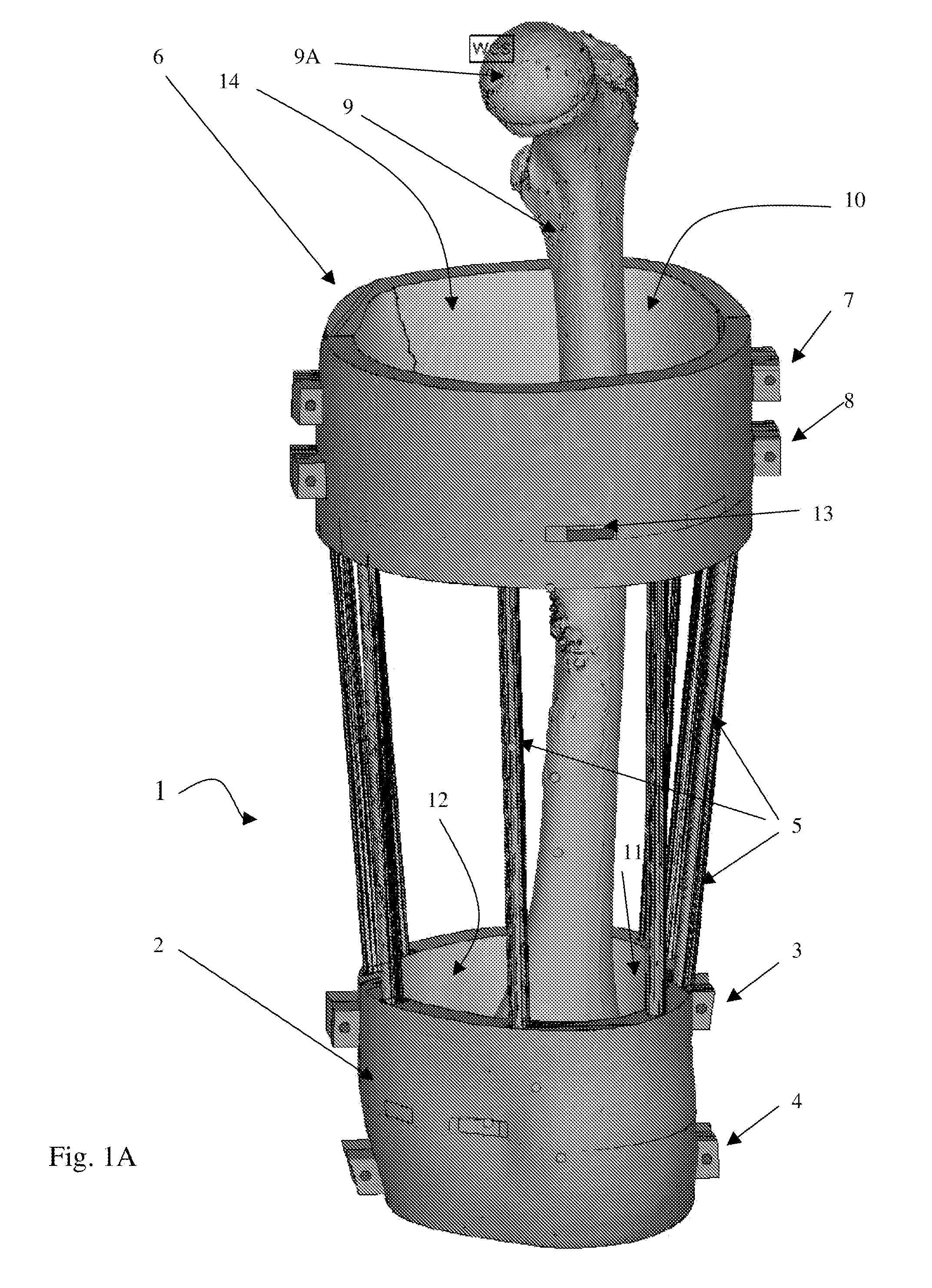
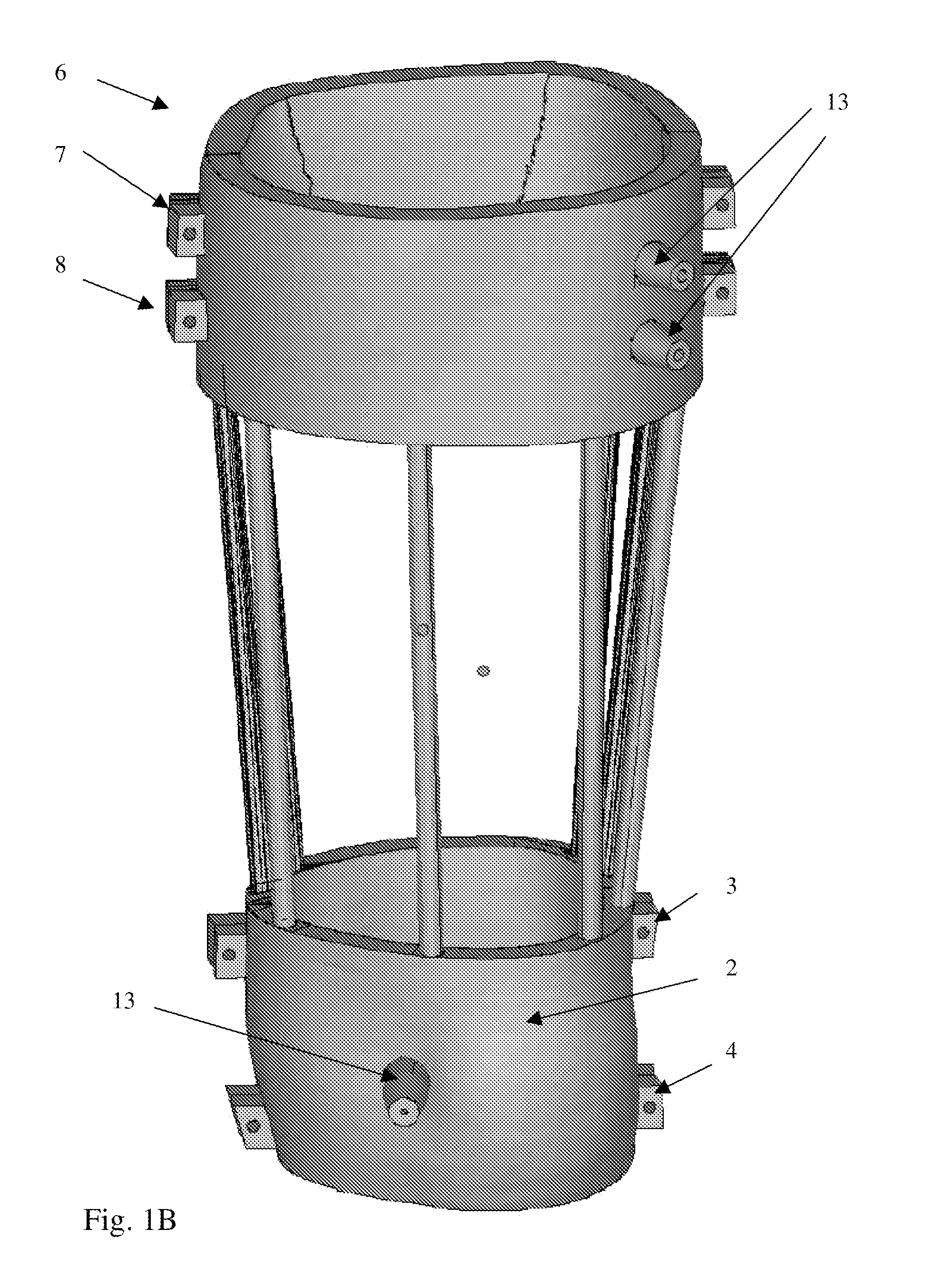
[0068]FIGS. 1A and 1B show schematic views of a surgical compression guide 1 according to the present invention.

[0069]A surgical compression guide 1 comprises a mechanical reference for a surgical, therapeutic or diagnostic tool, e.g. a surgical guide frame for medical treatments, in this case for surgery of the femur 9. A rigid structure 5 is provided, e.g. in the form of a frame. At least one functional guidance element 13 is provided. The guidance element 13 is fixed to the compression guide 1, e.g. optionally attachable directly or indirectly to the rigid structure 5 at a first location on the rigid structure. First and second means 6, 2 are provided for positioning and compression holding of the rigid structure 5 around parts of t...


PUM


Abstract

The present invention relates to a therapeutic, diagnostic or surgical tool, e.g. surgical guide frame for medical treatments, comprising: —a rigid structure, and —at least one functional guidance element (13), wherein the rigid structure comprises means for positioning and holding the rigid structure around a soft tissue area of a patient and includes means for compressing the soft tissue area surrounded by the positioning and holding means as well as to the use of such a therapeutic, diagnostic or surgical tool for medical treatments, especially in areas where the therapeutic, diagnostic or surgical tool, e.g. surgical guide is supported on soft tissue.

Description

TECHNICAL FIELD OF THE INVENTION [0001]The present invention relates to a surgical, therapeutic or diagnostic tool, e.g. a surgical compression guide for medical treatments, and methods of making and using the same.[0002]It applies more particularly, but not exclusively, to a surgical, therapeutic, or diagnostic tool, e.g. a surgical guide, for computer aided and computer planned treatments in areas where the guide is supported on soft tissue as well as methods of making and using the same.BACKGROUND OF THE INVENTION[0003]At present, there exists an increasing amount of surgical interventions that benefit from the use of medical image based patient specific surgical guides as described in patent applications US 2005 / 0203528 A1 and EP 1 486 900 A1, for instance.[0004]These guides mostly support on bone or teeth or areas of the body that have a good rigidity. In some situations soft tissue guides are used that support on soft tissue, but always in areas of the body where the soft tiss...

Claims


Application Information

Patent Timeline
Patent Type & Authority Applications(United States)
IPC IPC(8): A61B19/00
CPCA61B19/201A61B19/203A61B2019/205A61B19/54A61B19/5244A61B90/17A61B90/11A61B90/14A61B34/20A61B90/39A61B17/1739A61B17/1764A61B17/1782
Inventor VANCRAEN, WILFRIEDKEPPLER, LOUIS JAMESGEEBELEN, BENDILLE, JEROEN
Owner MATERIALISE NV
Why Eureka
Try Eureka