Tool apparatus system and method of use

a technology of tooling and tools, applied in the field of tooling tools, can solve the problems of difficult disengaging of components, damage to components, and disengagement of components

Active Publication Date: 2012-09-20
SNAP ON INC
View PDF5 Cites 43 Cited by
  • Summary
  • Abstract
  • Description
  • Claims
  • Application Information

AI Technical Summary

Problems solved by technology

Under-tightening the components could result in disengagement of the components.
Over-tightening the

Method used


Image

  • Tool apparatus system and method of use
  • Tool apparatus system and method of use
  • Tool apparatus system and method of use

Examples


example 1

Vehicle Repair Center

[0086]One embodiment of the system 112 is used by the tire and wheel industry to be used in the installation of automotive wheel lug nuts. This torque management system 112 provides the user with a hand operated electronic torque measuring tool 20 with a torque limited pneumatic driven power ratchet. The user is provided with an ability to retrieve and retain required lug nut torque values from a torque value database (one embodiment of the specifications database module 104) developed to original equipment manufacturers specifications.

[0087]A service representative of the tire and wheel industry facility inputs the programmed torque settings from the database. These settings are programmable to OEM or user defined torque settings. The system is advantageous for such uses because minimum technical knowledge of torque application is required by a technician to successfully apply the required torque and record torque data.

[0088]The system will reduce the possibili...

example 2

Infra-Red Communication Path

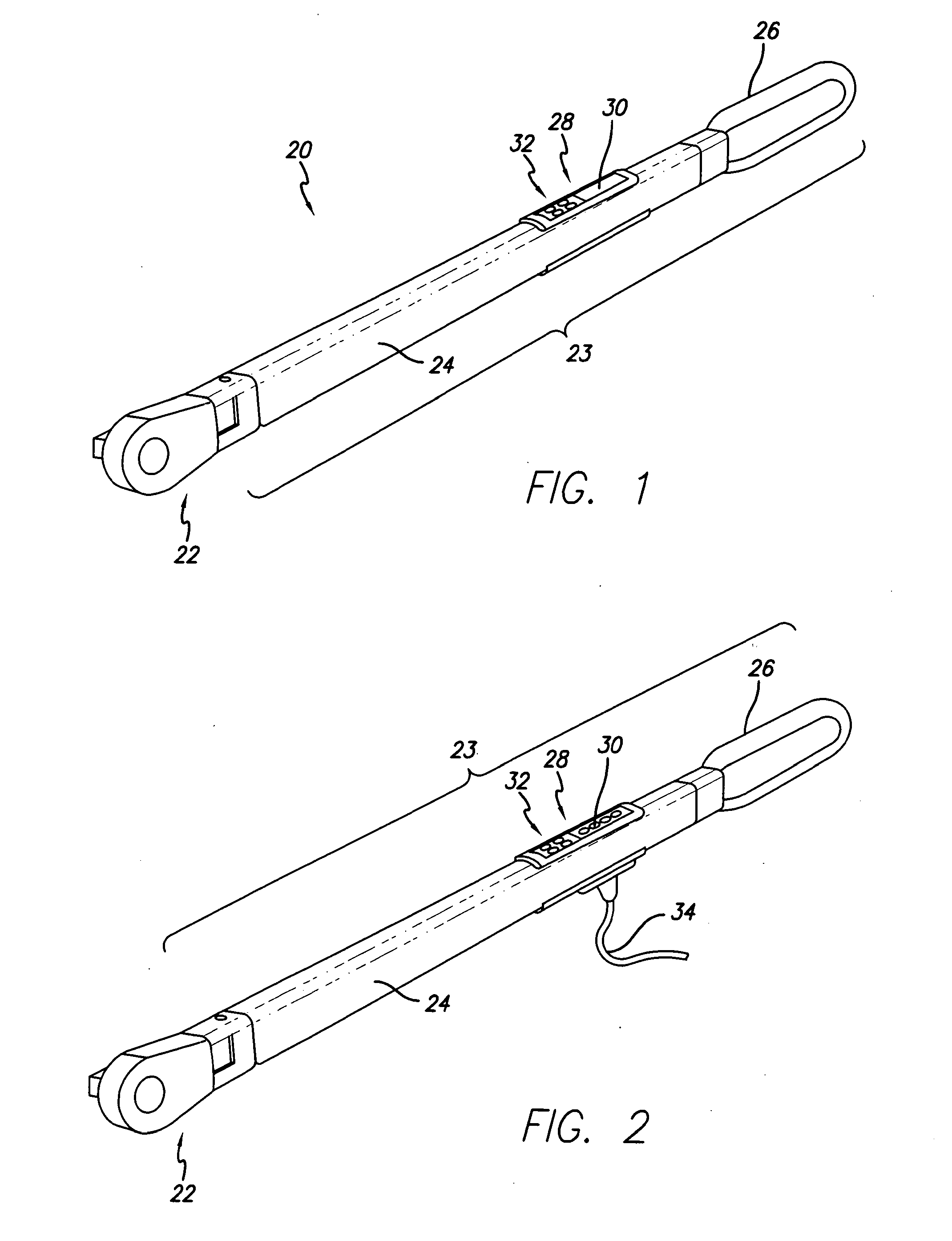
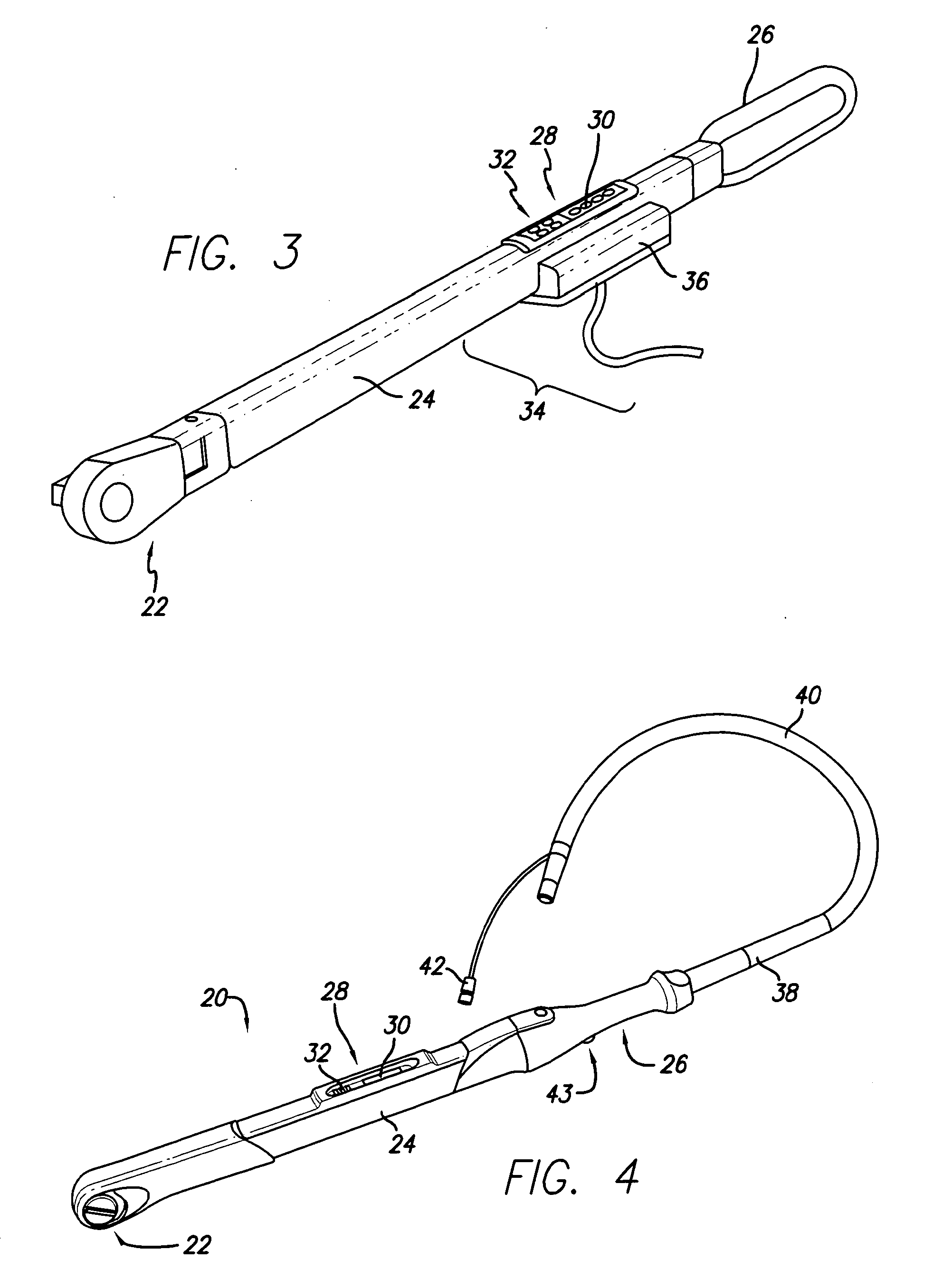
[0110]The hand held device 30 communicates with the shop management system 22. The technician selects a vehicle to work on from a pick list presented at the controller 28. Upon selection from the pick list, the control unit 46 queries its internal database for the vehicle associated with the repair order, or sends a request to the system 100 to query the specification database module 104 and retrieve the lug nut torque specifications for each wheel. Once the data is displayed, the technician can then beam, via infrared communication path 34, the specifications to the infrared port on the tool 20. Upon completion of the lug nut torqueing activities, the technician can beam the results of the activity back to the control unit 28 which can subsequently communicate the confirmation information and repair order number back to the shop management system 100 for storage.

example 3

Shop Management System and Control Unit Operation

[0111]Although a variety of shop management systems may be used in conjunction with the current system, one example of such a system is described for the purposes of illustrating the disclosed system. Reference to this shop management system is not intended to limit the present disclosure. The database used by the shop management system may be written in any commercially available programming language, may be developed using industry known database authoring programs such as Oracle, Access, SQL server, or may be developed from a combination of customizing database and generating software code to provide the functionality described hereinafter.

[0112]Programming for the database includes one or more software modules for providing the functions described hereinafter. The programming will also include modules for controlling and communicating with Input / Output interface to send control information to the tool 20 and / or control unit 46 in ...


PUM


Abstract

A system, and a method of using a system, for controlled tool operation. The method includes providing a tool used in a force application such as a such torque application. The tool communicates with a controller which can communicate with the tool, and to a display in communication with the tool and the controller. The controller can be programmed with operational information about a tool operation. Information related to the operational information is displayed to a user during use. Service information including at least information about an amount of force applied during use is recorded and stored in the controller. Also disclosed is a computerized system for controlled tool operation which sends operational instructions to the tool before use and retrieves service information from the tool after use.

Description

CROSS-REFERENCE TO RELATED APPLICATION(S)[0001]This application is a continuation in part of U.S. patent application Ser. No. 13 / 117,670, filed May 27, 2011; which is a continuation of U.S. patent application Ser. No. 11 / 679,113, filed Feb. 26, 2007, now U.S. Pat. No. 7,954,557, which is a continuation of U.S. patent application Ser. No. 11 / 025,225, filed Dec. 22, 2004, now U.S. Pat. No. 7,182,147, and a continuation-in-part of International Application No. PCT / US03 / 20426 with an international filing date of Jun. 27, 2003, which claims priority from U.S. Application No. 60 / 392,322, filed Jun. 27, 2002 and U.S. Application No. 60 / 414,191 filed Sep. 26, 2002, and is a continuation of International Application No. PCT / US03 / 30263 with an international filing date of Sep. 26, 2003 which claims priority from U.S. Application No. 60 / 414,191 filed Sep. 26, 2002, all of the foregoing being assigned to the assignee of the present disclosure and all of which are expressly incorporated herein b...

Claims


Application Information

Patent Timeline
IPC IPC(8): B25B23/14
CPCB25B21/00B25B23/1425B60B2900/3315B60B29/003B60B2900/3312B25B23/14B25B21/002B60B29/006B60B2900/3313G06Q10/20
Inventor LAWTON, CHRISLI, JIESAN, DE L.LEE, NATHAN
Owner SNAP ON INC
Why Eureka
Try Eureka