
Low Profile Solar Energy Conversion System

a solar energy and conversion system technology, applied in the direction of solar power wind motors, electric generator control, greenhouse gas reduction, etc., can solve the problems of deteriorating materials used in the solar collection area in prior art, loss of efficiency of solar energy absorption and energy transfer to air, and loss of efficiency of solar energy absorption and energy transfer in each main component of their design, so as to achieve efficient and economical process

Inactive Publication Date: 2012-09-20
HUNKA ROBERT
View PDF14 Cites 0 Cited by
  • Summary
  • Abstract
  • Description
  • Claims
  • Application Information

AI Technical Summary

Benefits of technology

[0013]The instant invention provides for an efficient, economical process of harnessing and utilizing solar energy by heating gas such as air and by capitalizing on, not only, its thermal nature, but its motive nature as well. This energy can be used in many fashions such as to generate electrical power created through turbines driven by airflow, for the drying of agricultural products, and for the condensation to potable water from a variety of processes, such as the drying of agricultural products, the evaporation of polluted water or from distilling the humidity in ambient air in high humidity locations. Furthermore, the latent heat released during condensation can supplement or replace the heat generated by solar energy. Removal of undesired liquids from industrial goods, either solid or porous, through evaporation and optional condensation as well as sequestration of objectionable fumes or pollution from liquids can also be achieved with the energy generated and can be incorporated into the invention.

Problems solved by technology

The disadvantage of this is that the earlier structures for converting solar energy into the movement of air lose efficiency in each of their main components of their design.
Solar energy absorption and energy transfer to air loses efficiency because some heat energy is transferred to areas that cannot subsequently heat the gas.
Furthermore, materials used in the solar collection area in prior art are subject to deterioration over time and needed to be designed for high energy transmission and high thermal insulating characteristics to prevent energy from escaping to the ambient environment.
These factors reduce the collection efficiency and can deteriorate considerably over the life expectancy of the structure.
Because the solar collection area of prior art is relatively flat, that area can collect dirt, sand, and debris as well as become graded by abrasion which blocks a percentage of the incident solar energy from heating the gas, leading to a degradation in efficiency of energy conversion.
The design of the output extraction device in prior art is restricted by the physical limitations of being located within the solar collection or vertical airflow structures.
Additionally these devices are subject to high temperatures as they harness energy from the escaping hot gassed which may adversely affect their service life.
The cost of the output produced goes up exponentially with height.
This increasing construction cost vs. output ratio significantly affects the payback on cost of construction

Method used


Image

  • Low Profile Solar Energy Conversion System
  • Low Profile Solar Energy Conversion System
  • Low Profile Solar Energy Conversion System

Examples


Embodiment Construction

[0029]While describing the invention and its embodiments, various terms will be used for the sake of clarity. These terms are intended to not only include the recited embodiments, but also all equivalents that perform substantially the same function, in substantially the same manner to achieve the same result.

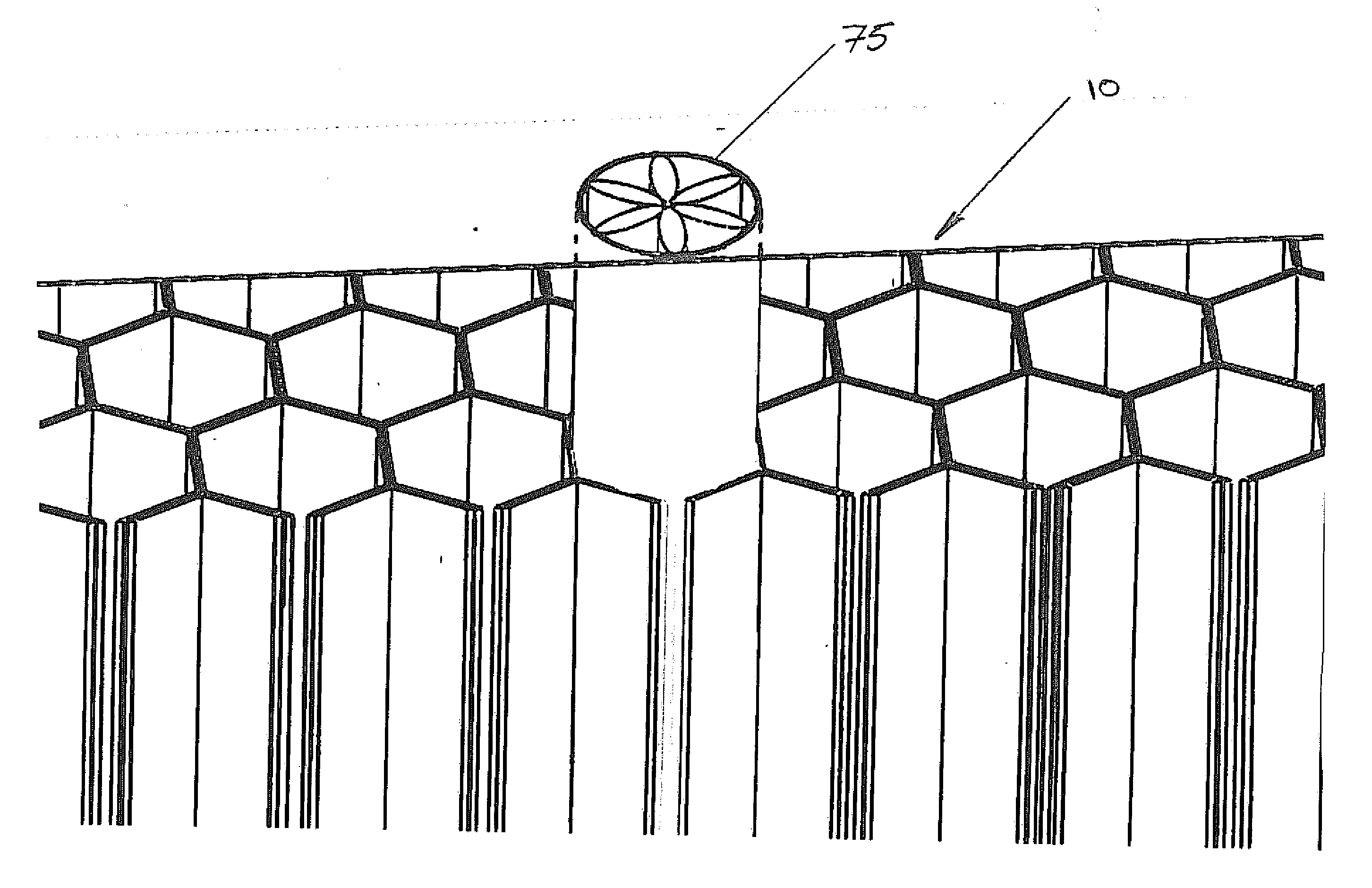
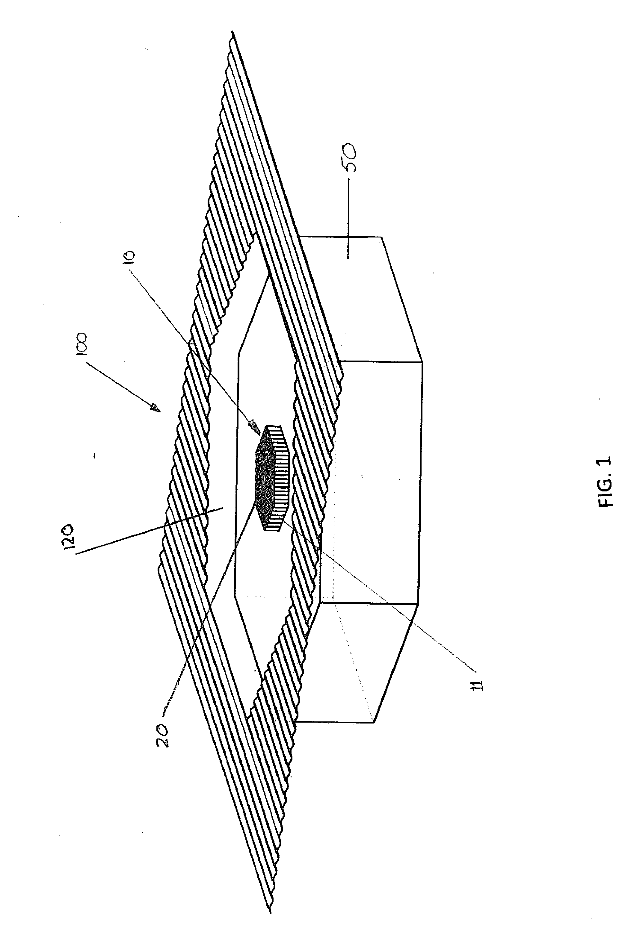
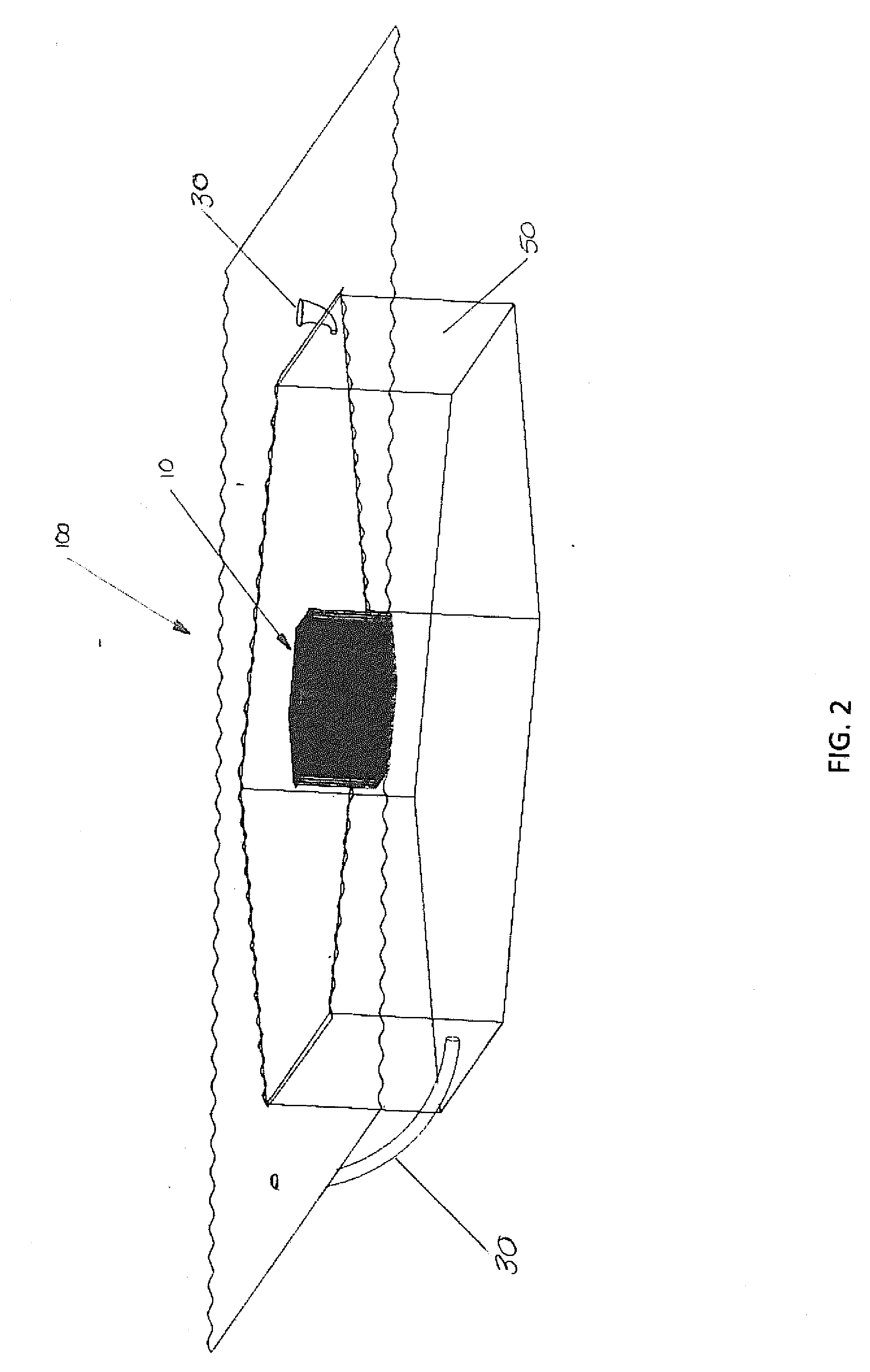
[0030]Now referring to FIG. 1 which discloses a preferred embodiment of the present invention, a low profile solar energy converter and storage system, generally reference by the numeral 100 for the use of capturing and converting solar energy into heat, electricity or rotational energy. The solar energy converter 100 comprises an insulated vault 50, at least air passage inlets 20, a heated air storage chamber 120, and a solar collection assembly, generally referenced by the numeral 10 which is represented in an exploded view in FIG. 3.

[0031]The system incorporates three main structures to produce a number of outputs driven by the flow of a gas. A first structural group, a sola...


PUM


Abstract

A novel cost effective low profile structure that converts and stores solar radiation into heat and electricity for controlled utilization. The inventive material incorporates a large insulated vault or chamber of substantial thermal mass connected to a series of inlet passages and to a solar collector assembly. As solar radiation is collected by the solar collector assembly a temperature gradient is created between the collector and the air that is within the vault resulting in air being drawn out of the chamber and through the collector assembly. This air movement is utilized to rotate turbines that are coupled to the inlet passages generating electricity. The hot air is also captured and utilized. The system provides for an efficient, economical process of harnessing and utilizing solar energy by capitalizing on not only on its thermal nature, but its motive nature as well.

Description

[0001]PRIORITY FILING[0002]This application is claiming the filing date of Sep. 10, 2010 of provisional patent application Ser. No. 61 / 403,153.BACKGROUND OF THE INVENTION[0003]1. Field of Invention[0004]The invention relates to solar energy conversion, specifically to an improved solar energy conversion and storage system utilizing ambient air .[0005]2. Related Art[0006]There are many modes and methods of generating and utilizing the energy of the sun utilizing the buoyant nature of heated gases. Most common prior art for producing electrical power required a large, relatively flat solar collection area coupled to an elongated cylindrical or chimney-like structure. Air movement would flow horizontally then change direction upward and out through a single, tall chimney which would then be coupled to a turbine or the like to generate electricity. The disadvantage of this is that the earlier structures for converting solar energy into the movement of air lose efficiency in each of thei...

Claims


Application Information

Patent Timeline
Patent Type & Authority Applications(United States)
IPC IPC(8): F03G6/04F01D15/10F24J2/34
CPCF03D9/007F03D9/02F05B2240/40F05B2250/283Y02E10/465F24J2/34F24J2/42Y02E10/44Y02E10/72F24J2/28F03D9/18F24S10/80F24S90/00F24S60/10Y02E10/46Y02E70/30
Inventor HUNKA, ROBERT
Owner HUNKA ROBERT
Learn More