Control device, control system, and control method

a control device and control system technology, applied in secondary cell servicing/maintenance, emergency power supply arrangements, greenhouse gas reduction, etc., can solve problems such as load not operating, and achieve the effect of increasing the operation time of loads

Inactive Publication Date: 2012-09-20
KYOCERA CORP
View PDF3 Cites 61 Cited by
  • Summary
  • Abstract
  • Description
  • Claims
  • Application Information

AI Technical Summary

Benefits of technology

[0005]Therefore, the present invention has been achieved in view of the above-described problems, and an object thereof is to provide a control device, a control system, and a control method, by which it is possible to increase the operation time of loads.
[0007]The control device as described above controls the degree of power consumption of loads provided in a consumer according to a remaining amount of the battery at the time of a self-sustained operation (for example, at the time of power outage). Consequently, it is possible to make the power supplied from the battery to the loads as small as possible and to operate the loads for a long time.
[0008]A second feature of the present invention is summarized as that the load control unit strengthens restriction of the power consumption as the remaining amount of the battery is smaller, and loosens the restriction of the power consumption as the remaining amount of the battery is larger.
[0016]According to the present invention, it is possible to increase the operation time of loads.

Problems solved by technology

However, in the above-mentioned conventional art, in the state in which a DC power supply may not generate electric power, for example, in the rain or at night when the DC power supply is a photovoltaic cell, since a remaining power amount of a battery is consumed in a short time, the loads may not operate.

Method used


Image

  • Control device, control system, and control method
  • Control device, control system, and control method
  • Control device, control system, and control method

Examples


first modification

(4.1) First Modification

[0070]Next, the first modification according to the above-mentioned embodiment will be described.

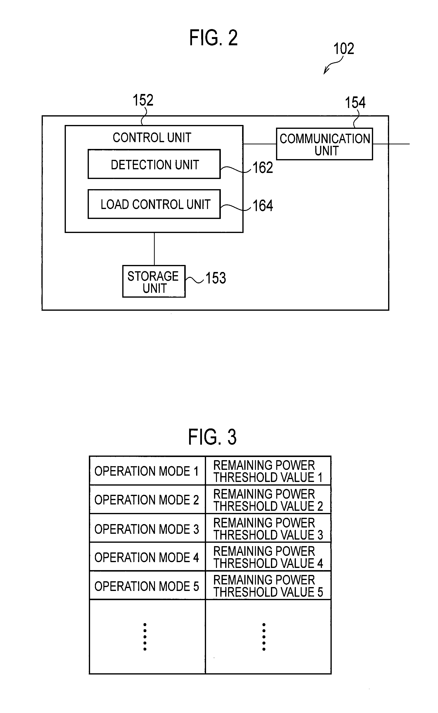
[0071]In the smart controller 102 according to the present modification, the storage unit 153 stores operation modes and remaining amount threshold values of the battery, which are associated with one another, for each of the illumination 110, the air conditioner 112, and the heat storage 114, which serve as a load, as illustrated in FIG. 8. Specifically, the storage unit 153 stores operation modes 1 to 5 which are associated with remaining amount threshold values A1 to A5 of the illumination 110, remaining amount threshold values B1 to B5 of the air conditioner 112, and remaining amount threshold values C1 to C5 of the heat storage 114, respectively. In other words, the storage unit 153 stores remaining amount threshold values and operation modes, which are associated with one another and different from one another, for each of the illumination 110, the air condi...

second modification

(4.2) Second Modification

[0084]Next, the second modification according to the above-mentioned embodiment will be described.

[0085]In the remote control sensor unit 109 according to the present modification, the motion sensor 176 detects a human (a user) staying in a predetermined area. Here, the predetermined area indicates an area of a room provided with a load such as the illumination 110 and the remote control sensor unit 109. In addition, in the smart house 10, when there are a plurality of rooms provided with loads, the remote control sensor unit 109 having the motion sensor 176 may be provided in each room.

[0086]Furthermore, in the remote control sensor unit 109 according to the present modification, when the motion sensor 176 has detected a human, the motion sensor 176 transmits detection information to the smart controller 102 via the communication unit 174 and the in-house communication line 160, wherein the detection information includes information indicating the presence ...


PUM


Abstract

Provided is a smart controller (102) that detects the amount of power remaining in a storage battery (108). The smart controller (102) also determines the load operation modes of an illumination (110), an air conditioning apparatus (112), and a heat storage apparatus (114) to become modes with lower power consumption when the remaining amount of power becomes lower, by comparing the detected remaining amount of power, and a threshold value in a predetermined correlation between operation modes and threshold values for the remaining amount of power, and thereby controls the illumination (110), the air conditioning apparatus (112), and the heat storage apparatus (114), as loads.

Description

TECHNICAL FIELD[0001]The present invention relates to a control device provided in a power consumer including a DC power supply, loads, and a battery capable of storing power from the DC power supply, and controlling the loads, a control system provided with the control device and a device capable of operating a plurality of loads, and a control method in the control device.BACKGROUND ART[0002]In recent years, in view of the reduction of an environment load, a system is gradually becoming available in which a DC power supply such as a photovoltaic cell is provided in a house and the like which are power consumers, electric power required by devices in the house is supplied by power generated by the DC power supply, a battery in the house is charged by surplus power (for example, refer to Patent Document 1), and the battery is discharged to supply power to loads at the time of a self-sustained operation (for example, at the time of power outage) in which no power from an electric pow...

Claims


Application Information

Patent Timeline
Patent Type & Authority Applications(United States)
IPC IPC(8): H02J7/34
CPCH01M10/44Y04S20/248H02J3/32H01M10/465H01M2010/4271H02J3/383H02J9/062Y02E70/30Y02E10/563Y02E10/566H02J3/14H02J2003/143Y02B10/72Y02B70/3291H01M10/48H02J2310/14H02J2300/24H02J3/381Y02B70/30Y02E10/56Y02E60/10Y02B10/70
Inventor KIUCHI, KAZUYAKUSAFUKA, KAORUWATANABE, TADAYUKISHICHIRI, KAZUMASAIWABUCHI, AKINORI
Owner KYOCERA CORP
Why Eureka
Try Eureka