
Transverse device phase shifter

Active Publication Date: 2012-09-20
RAYTHEON CO
View PDF5 Cites 16 Cited by
  • Summary
  • Abstract
  • Description
  • Claims
  • Application Information

AI Technical Summary

Problems solved by technology

The large current pulse requirements, as well as, the multiple pulses make the bias circuitry complex, costly and limited in speed.
The phase shifters are also lossy.
As the operating frequency increases, the size and coupling of such phase shifters to associated circuits is a major issue.
Again, rather complex, external bias drive circuits are required to implement the switch bias.
The PIN diode based systems require large levels of bias current, which further complicates the architecture.
The individual switches are also lossy.
This material however, when employed in a phase shifter configuration requires ten thousand (10 Kv) volts of bias and is an extremely lossy medium for the propagation of RF energy.

Method used


Image

  • Transverse device phase shifter
  • Transverse device phase shifter
  • Transverse device phase shifter

Examples


Embodiment Construction

[0014]In the following detailed description and in the several figures of the drawing, like elements are identified with like reference numerals. The figures are not to scale, and relative feature sizes may be exaggerated for illustrative purposes.

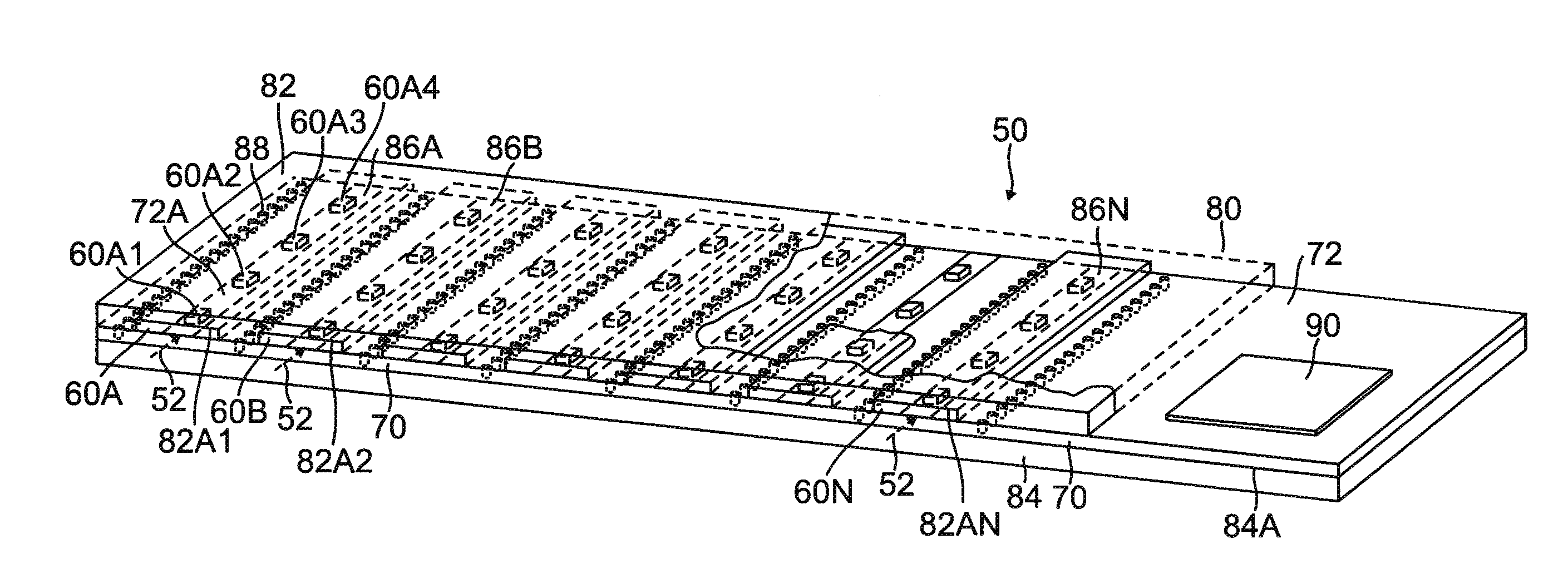
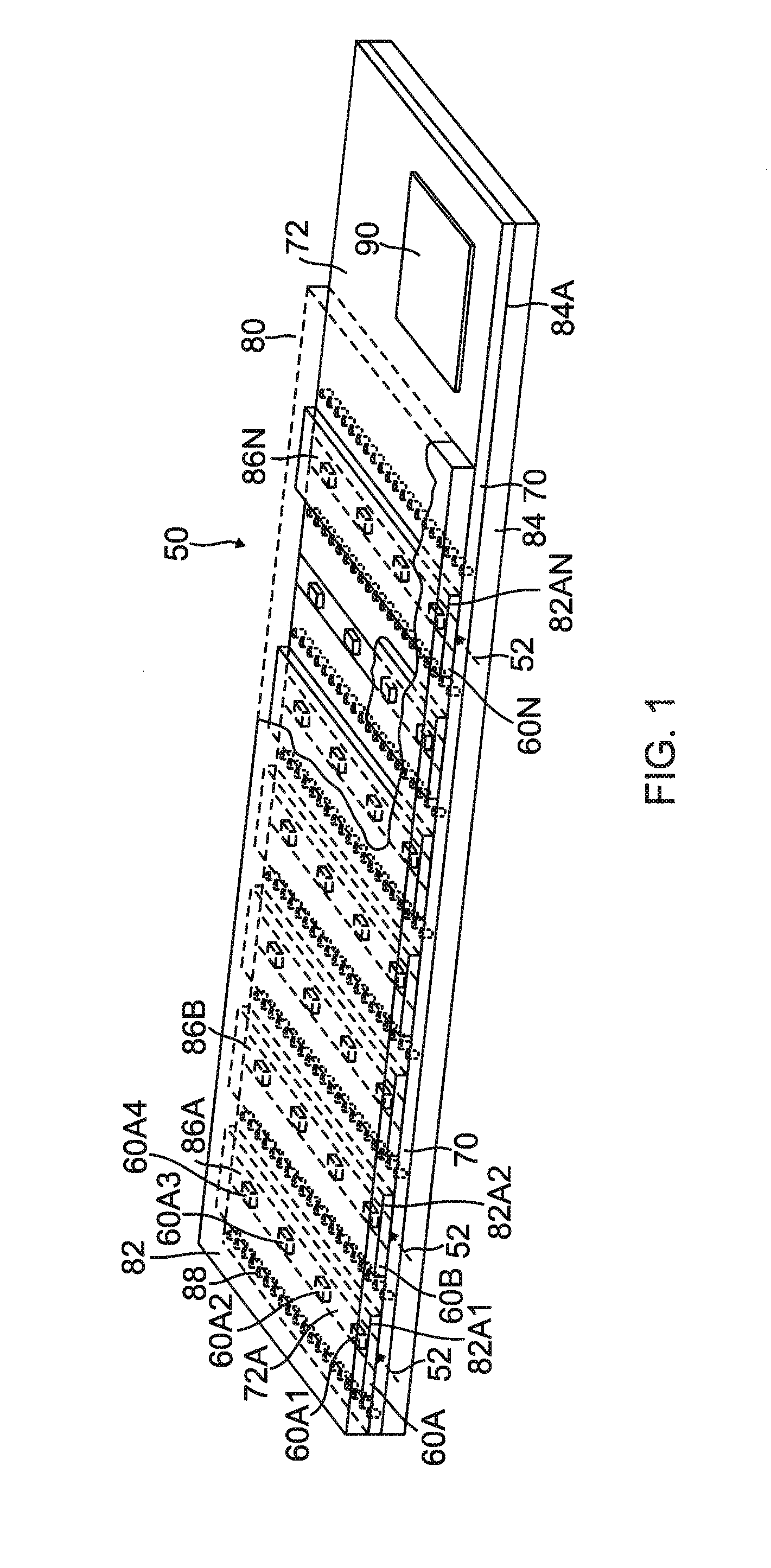
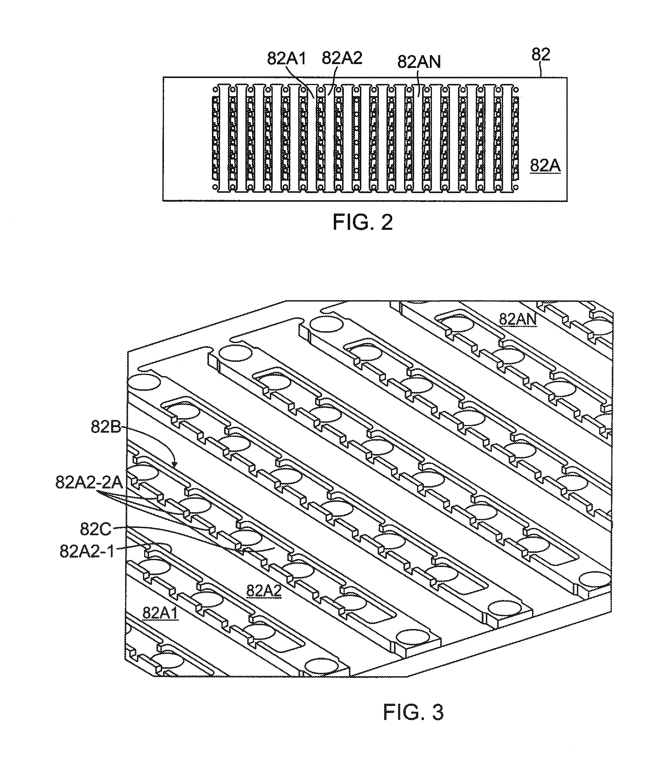
[0015]FIG. 1 depicts an exemplary embodiment of a phase shifter device array 50 operable at microwave (or millimeter-wave), hereinafter sometimes referred to as a “Microstrip Transverse Device Array” (“MTDA”). The exemplary structure shown in FIG. 1 includes seven “boxed” microstrip phase shifters 60A, 60B . . . 60N, each with four tuning elements cascaded along the propagation direction. For example, phase shifter 60A includes tunable elements 60A1, 60A2, 60A3 and 60A4, arranged along the propagation direction indicated by arrow 52. The phase shifters employ discrete semiconductor devices, typically varactor diodes, (Schottkys, FETs, etc. may also be employed) as the tunable element. The discrete semiconductor devices are mounted on a die...


PUM


Abstract

A phase shifter operable at microwave or millimeter-wave frequencies includes a dielectric substrate with a bottom surface having a conductive ground plane layer and a conductive patterned layer formed on a top surface to define a conductor pattern. A series of active tuning elements is mounted on the top surface and cascaded along a propagation direction in a spaced arrangement along a longitudinal extent. A housing structure includes a bottom housing structure with a planar conductive bottom surface for contacting the ground plane layer, and a top housing structure fabricated with a channel which extend along the longitudinal extent and provide clearance for the active tuning elements. A bias circuit is connected to the respective series of active tuning elements.

Description

[0001]This invention was made with Government support under Contract No. W911 QX-04-C-0108 awarded by the Department of the Army. The Government has certain rights in this invention.BACKGROUND[0002]Ferrite materials are the common method for electronic phase shifter implementation. Ferrites are anisotropic, i.e., the phase shift of the energy in one direction is not replicated in the reverse direction. Ferrite phase shift is accomplished by applying a large current pulse, typically several amps in value, to the ferrite to establish a change in the large magnetic field and thereby adjusting the phase propagation characteristic of the material. Due to the hysteresis phenomena of ferrites, in order to change the phase another large current pulse is required to reset the phase to a stable reference phase state, followed by a second large pulse to establish the final phase state. The large current pulse requirements, as well as, the multiple pulses make the bias circuitry complex, costly...

Claims


Application Information

Patent Timeline
IPC IPC(8): H01P1/18H01Q19/06
CPCH01P1/184H01P1/185H01Q21/0037H01Q11/02H01Q21/0018H01Q3/46
Inventor LEWIS, ROBERT T.ROBERTSON, RALSTON S.HENDERSON, WILLIAM H.
Owner RAYTHEON CO
Learn More