Fixing device with resistance heating element capable of accurately generating heat and image forming apparatus with fixing device

a technology of resistance heating element and fixing device, which is applied in the direction of electrographic process apparatus, instruments, optics, etc., can solve the problems of resistance heating element temperature not reaching the target temperature, requiring a long time to warm up, and changing calorific value, so as to achieve the effect of minimizing the deformation of the contact member

Inactive Publication Date: 2012-09-20
RICOH KK
View PDF7 Cites 68 Cited by
  • Summary
  • Abstract
  • Description
  • Claims
  • Application Information

AI Technical Summary

Benefits of technology

[0015]Accordingly, the present invention provides a novel fixing device that comprises an endless flexible fixing member to heat and fuse a toner image by rotating in a prescribed direction, a pressing roller, and a contact member secured on an inner circumferential surface side of the fixing member to contact the pressing roller via the fixing member forming a nip on a front surface of the fixing member. A support member is provided to back up the contact member against pressure of the pressing member to minimize deformation of the contact member. A heating element is provided and is extended along the fixing member other than the nip on an inner circumferential surface side of the fixing member to generate heat. The fixing member contacts the heating element via a gap of a prescribed size or directly contacts the heating element by a prescribed pressure when it is rotating, and continuously separates from the at least one heating element by a prescribed distance greater than the size of the gap when it stops rotating.
[0022]In yet another aspect of the present invention, an image forming apparatus comprises a toner image forming device to form a toner image and a fixing device to fix the toner image onto a recording medium. The fixing device includes an endless flexible fixing member to heat and fuse a toner image by rotating in a prescribed direction, a pressing roller, and a contact member firmly disposed on an inner circumferential surface side of the fixing member to contact the pressing roller via the fixing member while forming a nip on a front surface of the fixing member. A support member is provided to back up the contact member against pressure of the pressing member to minimize deformation of the contact member. A heating element is extended along the fixing member other than the nip on an inner circumferential surface side of the fixing member to generate heat. The fixing member contacts the heating element via a gap having a prescribed size or directly contacts the heating element by a prescribed pressure when it is rotating, and continuously separates from the heating element by a prescribed distance greater than the size of the gap when it stops rotating.

Problems solved by technology

However, a problem with the above-described fixing systems is that they require a long time to warm up due to bad durability, poor temperature stability, and large heat capacity, as well as slow temperature rising of the belt.
However, it turns out that a resistance heating element is such that its calorific value changes with temperature even at constant voltage, because the heating element's internal resistance changes.
As a result, even if the temperature of the fixing member is detected and a prescribed voltage is applied to the resistance heating element to control temperature, the temperature of the resistance heating element does not achieve the target temperature.
Accordingly, the temperature of the fixing belt cannot ultimately be controlled as intended.

Method used


Image

  • Fixing device with resistance heating element capable of accurately generating heat and image forming apparatus with fixing device
  • Fixing device with resistance heating element capable of accurately generating heat and image forming apparatus with fixing device
  • Fixing device with resistance heating element capable of accurately generating heat and image forming apparatus with fixing device

Examples


Embodiment Construction

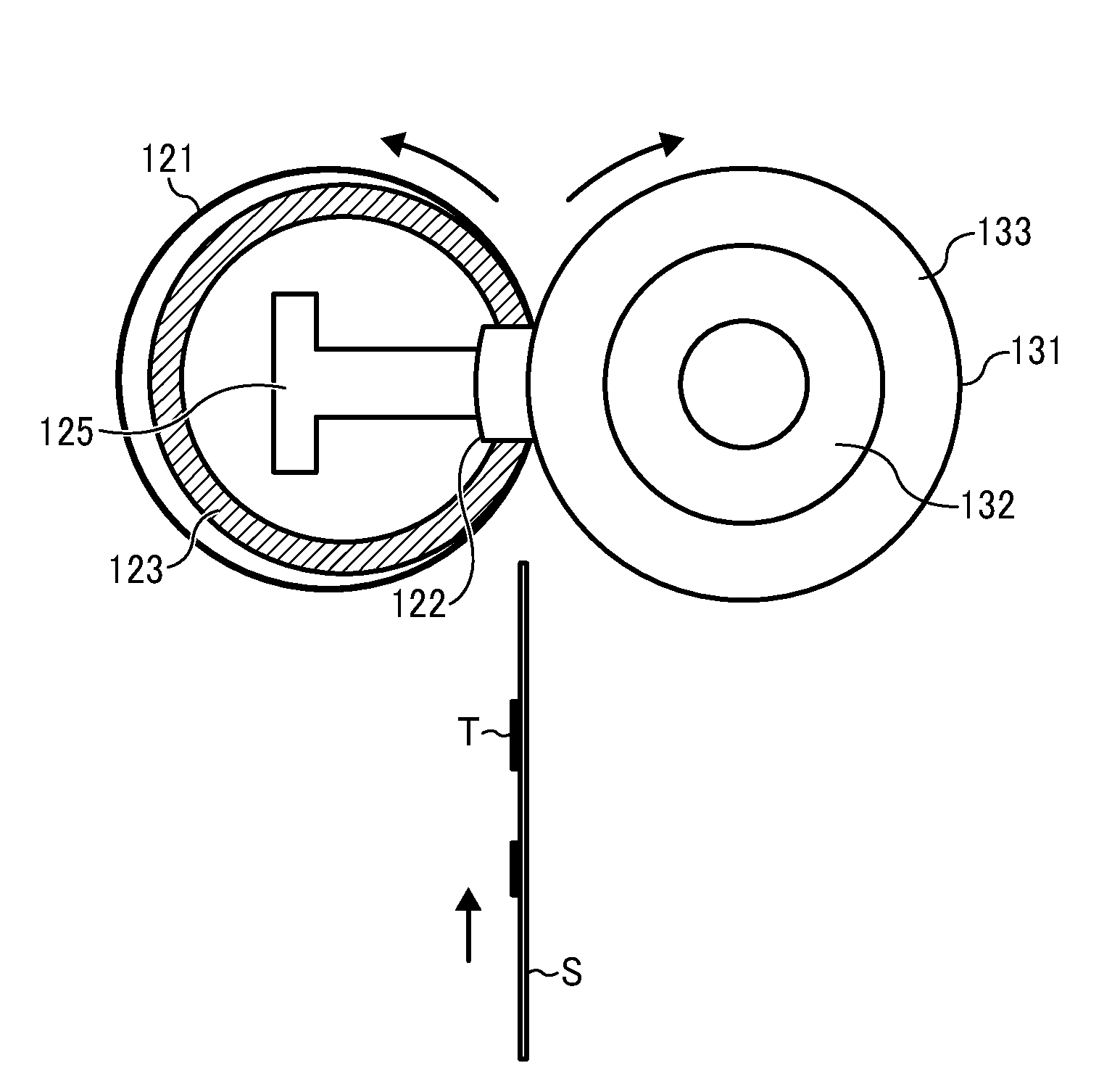
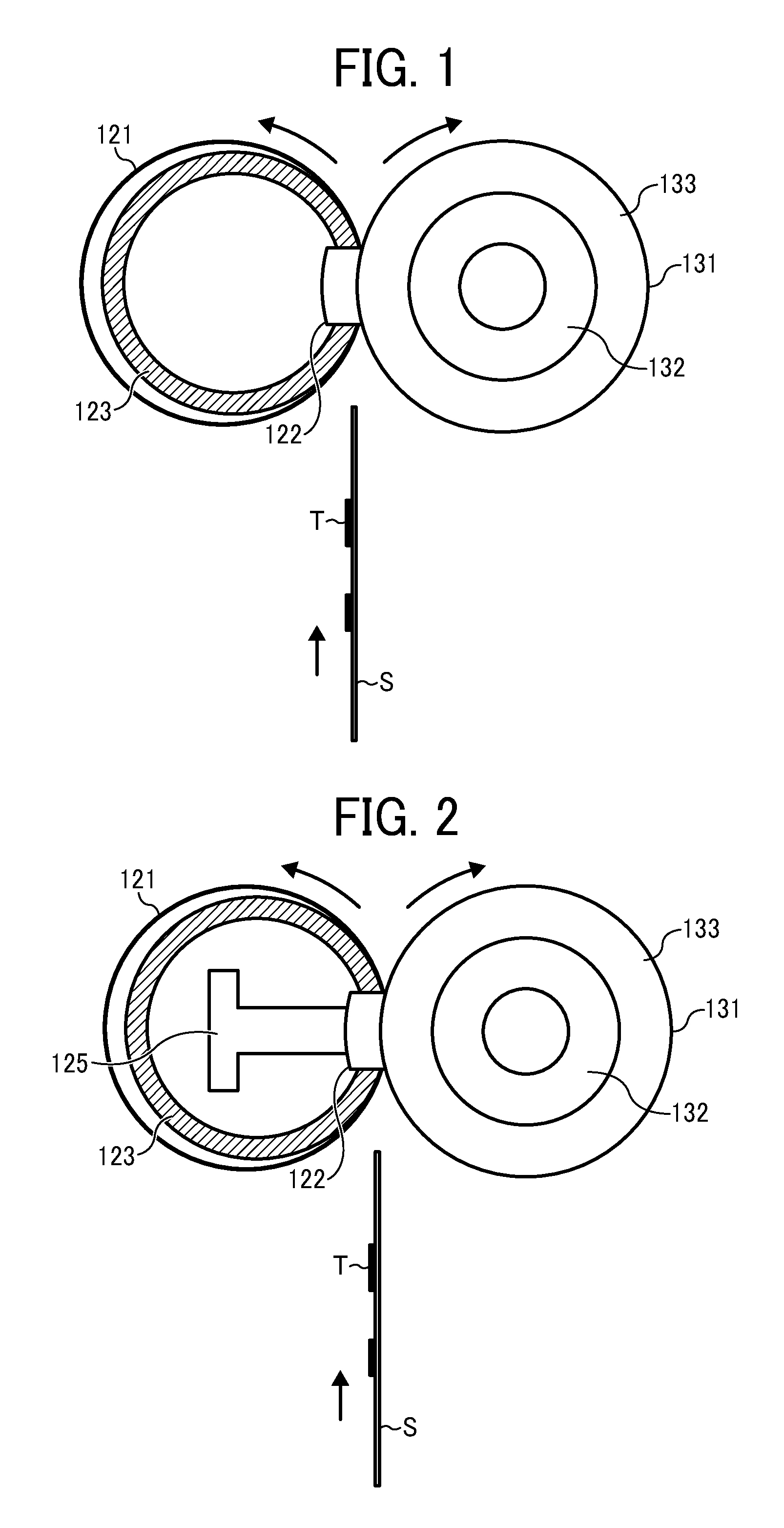
[0036]Referring now to the drawings, wherein like reference numerals designate identical or corresponding parts throughout the several views thereof and in particular to FIG. 1, a fixing device is described.

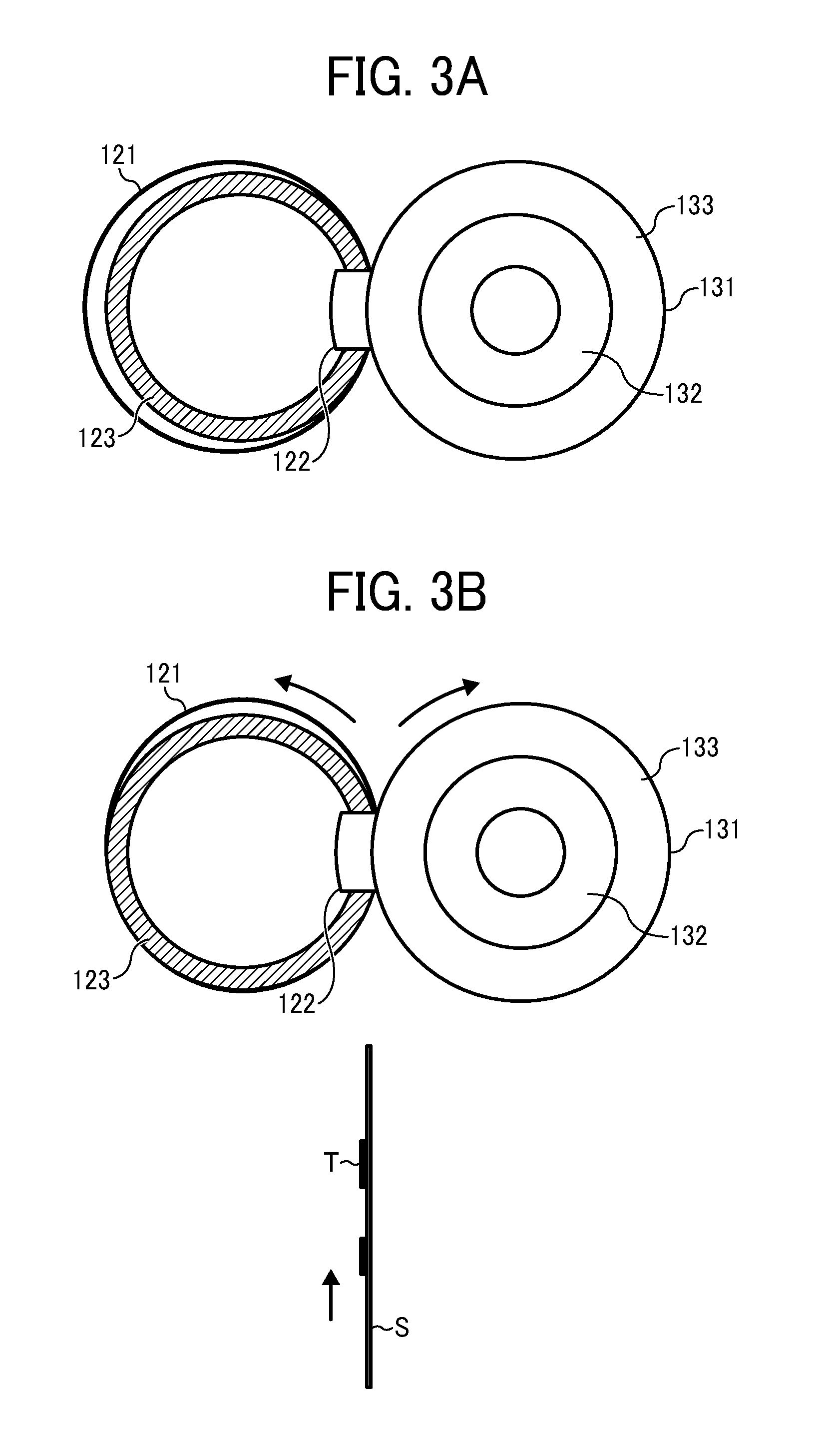
[0037]As shown, the fixing device mainly consists of a fixing belt 121 serving as a fixing member, a contacting member 122, a resistance heating element 123, and a pressing roller 131 serving as a pressing member. The fixing belt 121 is a thin-flexible endless belt and travels and circulates in a direction shown by arrow in FIG. 1, i.e., counter-clockwise. In an interior of the fixing belt 121 (e.g. on the inner circumferential surface side), the contacting member 122 and the resistance heating unit 123 or the like are secured. The fixing belt 121 is pressed by the contacting member 122 and forms a nip between itself and the pressing roller 131.

[0038]Each end of the contacting member 122 in its widthwise direction is securely supported by each side plate, not illustrated, dispose...


PUM


Abstract

In a fixing device, a heating element is extended along a fixing member at a location other than a nip on an inner circumferential surface side of the fixing member to generate heat. The fixing member contacts the heating element either indirectly via a gap of a prescribed size or directly contacts the heating element by with a prescribed pressure when the fixing member is rotating, and continuously separates from the heating element by a prescribed distance greater than the size of the gap when the fixing member stops rotating.

Description

CROSS-REFERENCE TO RELATED APPLICATION[0001]This patent application is based on and claims priority pursuant to 35 U.S.C. §119 to Japanese Patent Application No. 2011-059596, filed on Mar. 17, 2011 in the Japanese Patent Office, the entire disclosure of which is hereby incorporated by reference herein.BACKGROUND OF THE INVENTION[0002]1. Field of the Invention[0003]The present invention relates to a fixing device and an image forming apparatus, in particular to a fixing device and an image forming apparatus employing a belt type fixing system using a belt as a fixing member, which is capable of accurately generating heat.[0004]2. Description of the Related Art[0005]As is well known, in an image forming apparatus employing an electro-photographic system, an electrostatic latent image is formed on a photoconductor as a latent image bearer and is rendered visible with toner to form a toner image. Subsequently, the toner image is transferred onto a recording medium, such as a recording s...

Claims


Application Information

Patent Timeline
Patent Type & Authority Applications(United States)
IPC IPC(8): G03G15/20
CPCG03G15/2053G03G2215/2035G03G15/2039
Inventor YOSHINAGA, HIROSHIYOSHIKAWA, MASAAKIISHII, KENJIARAI, YUJITAKAGI, HIROMASAIWAYA, NAOKITOKUDA, TETSUOFUJIMOTO, IPPEIYAMAGUCHI, YOSHIKIIKEBUCHI, YUTAKASESHITA, TAKUYAYOSHIURA, ARINOBUIMADA, TAKAHIROGOTOH, HAJIMESHIMOKAWA, TOSHIHIKO
Owner RICOH KK
Why Eureka
Try Eureka