Techniques for providing custom-formed implants

a technology of medical implants and custom-made materials, applied in the field of custom-made medical implants, can solve the problems of unsatisfactory cosmetic appearance, disadvantageous application of such materials, and often further disadvantages of applying materials on the surface of dental or other medical implants

Inactive Publication Date: 2012-09-20
JOSEPH MANISCALCO DDS PC
View PDF14 Cites 15 Cited by
  • Summary
  • Abstract
  • Description
  • Claims
  • Application Information

AI Technical Summary

Benefits of technology

[0048]Reference numbers in the drawing have three or more digits: the two right-hand digits are reference numbers in the drawin

Problems solved by technology

Where a surface of a dental implant such as one at least partly of titanium may be at least partially visible in vivo, this can result in an undesirable cosmetic appearance, as cosmetic appearance may be particularly determined by differences in color.
Thus in general, applied layers of such materials are disadvantageous for cosmetic reasons, but in some circumstances such as a request of a particular patient are preferred.
Applied layers of materials on a surface of a dental or other medical implant frequently have further disadvantages compared to other surface treatments such as anodization.
Further, applied layers in general may be prone to fracture, separation, poor durability, cracking, splitting, pitting, or other modes of failure.
Another disadvantage of many forms of an applied layer of material is that the applied layer may create an environment that increases the probability of bacterial growth, such as bacterial growth that can lead to dental caries or other infections.
One problem with the known solution of implanting standardized implant components with a surface treatment is that in many instan

Method used


Image

  • Techniques for providing custom-formed implants
  • Techniques for providing custom-formed implants
  • Techniques for providing custom-formed implants

Examples


first embodiment

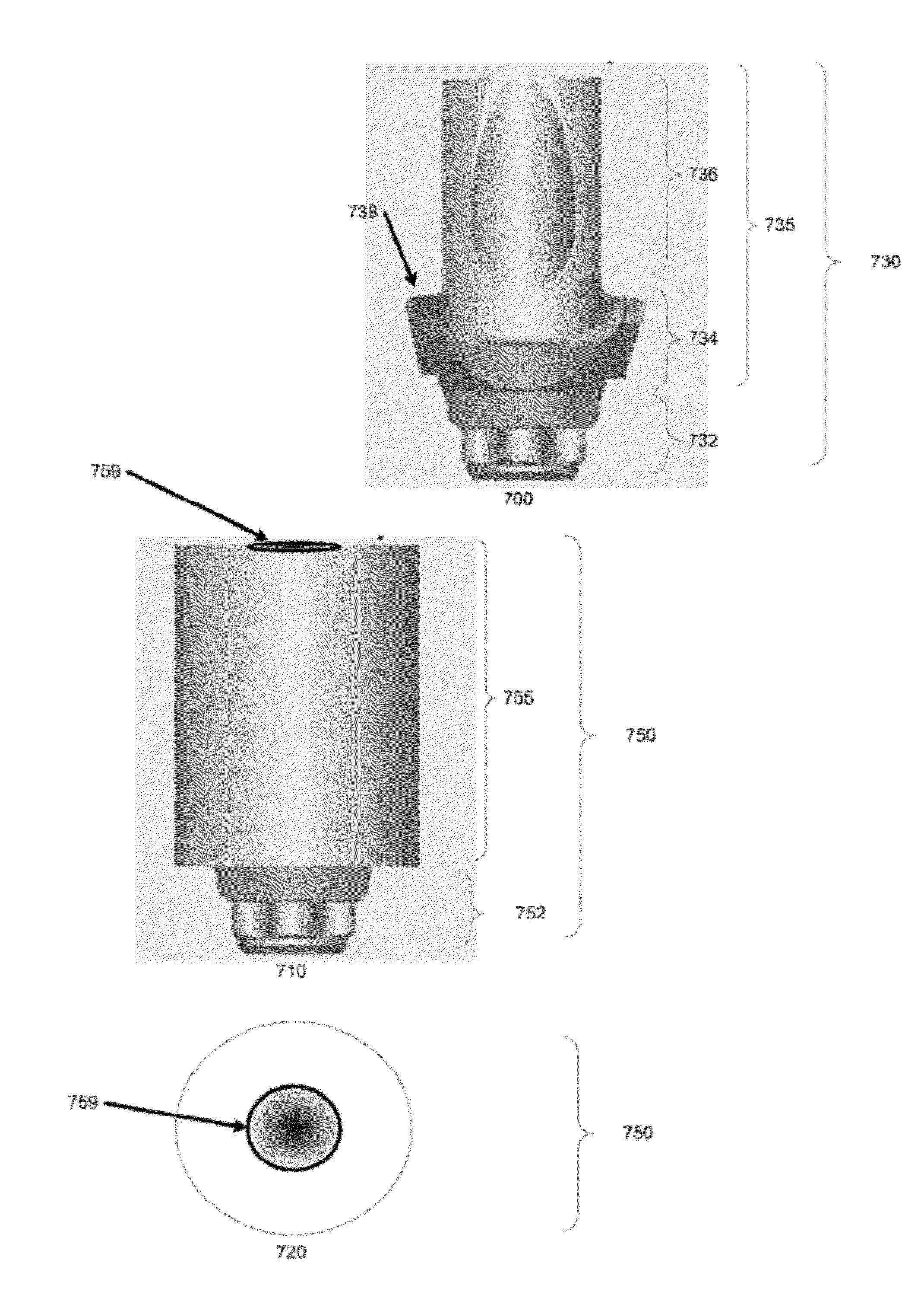
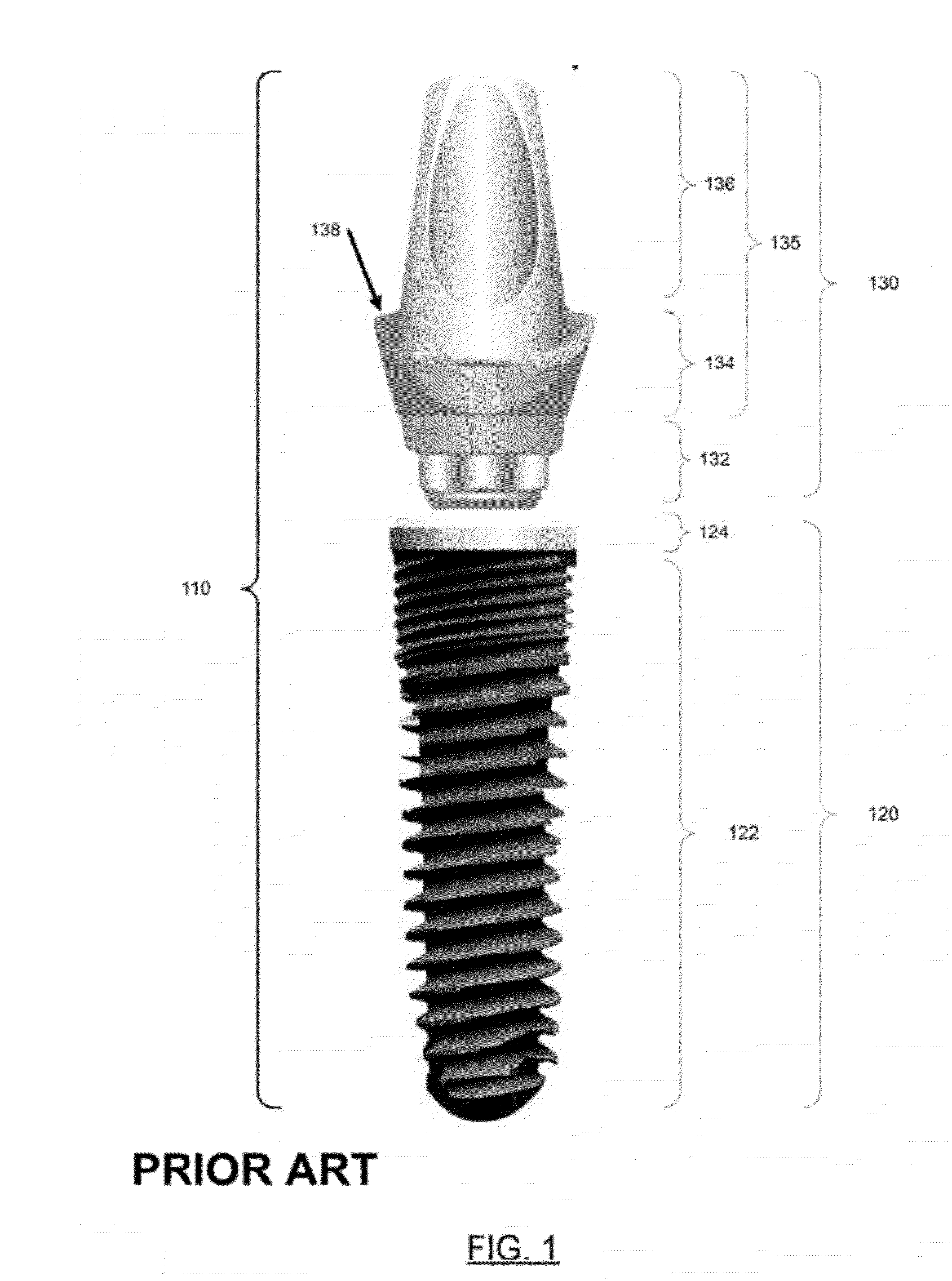
[0079]a blank dental implant abutment 730 is shown in side view 700. The base portion 732 of the blank abutment component 730 has similar dimensions to the base portion 132 of the standardized abutment of FIG. 1 and FIG. 2, and thus may be used compatibly with the standardized body component 120 of FIG. 1. In some embodiments, at least a portion of the base portion 732 has identical dimensions to base portion 132 of FIG. 1.

[0080]Other dimensions of the blank abutment component 730 are different from those of the standardized abutment component of FIG. 1, for example the chimney portion 736 may have greater diameter as shown, to facilitate the removal of material to custom-form the blank component to a desired form, such as a form that may be greater or lesser in different dimensions than the standardized component, or in portions have an entirely different form.

[0081]As can be seen from FIG. 1 and view 700, the shelf portion 738 of the blank component 730 is wider than the correspon...

embodiment 750

[0083]The supra fixture portion 755 of blank abutment component embodiment 750 may be cylindrical as shown, and not have been pre-formed to have a shelf portion or other standardized portions like that of the standardized abutment of FIG. 1. The supra fixture portion 755 is largely featureless, on its exterior intended to be custom-formed. In the center of the top surface of the supra fixture portion 755, a threaded cylindrical screw hole 759 is visible to accept an attachment screw (not shown) compatibly to a similarly threaded hole as may be in the abutment component of FIG. 1 for attachment of either abutment to the base component 120.

[0084]The top view 720 shows the top of supra fixture portion 755 of the blank abutment 750. As shown, the screw hole 759 is centered in the top surface of supra fixture portion 755. The supra fixture portion may be custom-formed by the removal of material to a custom-formed form for use in a particular patient. In some embodiments, the screw hole 7...

embodiment

of FIG. 8

[0093]FIG. 8 illustrates steps performed by two entities: a dental or medical practitioner (henceforth dental practitioner or practitioner) who custom-forms an implant component, and an entity that performs the surface treatment (henceforth surface-treater). Steps performed by the practitioner are to the left of the dotted line 833, and steps performed by the surface-treater are to the right of the dotted line 833.

[0094]The embodiment of FIG. 8 starts at the step of 805, in which the dental practitioner selects a standardized implant component for approximate fit in a particular patient's mouth. The component may also be a blank component, or other kind of component.

[0095]As shown at the step 815, after step 805 the practitioner places the component in the patient's mouth in situ, or in an exemplary alternative, in a model of the patient's mouth, and next at the step 845 modifies the component to custom-forming it, such as by removing and / or adding material to achieve a des...


PUM


Abstract

Techniques for providing medical implants that have been custom-formed for a particular patient for surface treatment to alter properties of a surface of an implant component. A dental abutment implant component, custom-formed by removing or adding material or by providing an electronic or other specification for its fabrication, is provided to a third party for a surfaced treatment to be, performed. After the abutment with surface treatment is received from the third party, it may be moved to the patient's body. One preferred kind of surface treatment employs anodization of a dental metal material such as titanium to give a pink color for improved cosmetic results. Other kinds of surface treatment including bonding may also be used. A blank implant component that has a first portion compatible with a standardized implant component, and a second portion expressly intended to be custom-formed by removing material.

Description

CROSS-REFERENCE TO RELATED APPLICATIONS[0001]The subject matter of this patent application is related to and claims priority from U.S. Provisional Patent Application Ser. No. 61 / 453,791, Maniscalco, Techniques for Dental Implants, filed 17 Mar. 2011, which is hereby incorporated by reference in its entirety.STATEMENT REGARDING FEDERALLY SPONSORED RESEARCH OR DEVELOPMENT[0002]Not applicable.REFERENCE TO A SEQUENCE LISTING[0003]Not applicable.BACKGROUND OF THE INVENTION[0004]This invention generally relates to techniques for providing custom-formed medical implants for individual patients. More specifically, this invention relates to techniques for providing dental implant components such as abutments that are custom-formed for a particular patient and have a surface that is visible either directly or partially through the gums or through material of a prosthetic crown to achieve an improved cosmetic appearance of the custom-formed implant component.Description of Related Art[0005]As ...

Claims


Application Information

Patent Timeline
IPC IPC(8): A61C8/00
CPCA61C8/0013A61C13/0022A61C8/005A61C8/0018
Inventor MANISCALCO, JOSEPH
Owner JOSEPH MANISCALCO DDS PC
Why Eureka
Try Eureka