
Flash Memory Device and Control Method

a flash memory device and control method technology, applied in the field of flash memory devices and electronic units, can solve the problems of unfavorable adjustment and unscrupulous operation parameters, and achieve the effect of different operating efficiency, and increasing the operational efficiency of the flash memory devi

Active Publication Date: 2012-09-20
RPX CORP
View PDF6 Cites 86 Cited by
  • Summary
  • Abstract
  • Description
  • Claims
  • Application Information

AI Technical Summary

Benefits of technology

[0034]The advantage of providing a method which varies the operating parameters or the parameter values in one or more operating registers of a flash memory device is that the operational efficiency of the flash memory device will be increased. Relatively low electrical stimuli may be used initially to write to, read from and erase the flash cells in the flash memory device. As state changes occur over time, the flash cells in the flash memory device will begin to degrade and it will be necessary to move thresholds and / or increase the electrical stimuli applied to the flash memory device in order to ensure that adequate write, read and / or erase commands are carried out. Essentially, the present invention varies the operating parameters by changing the corresponding register value over the operating lifetime of the flash memory device.
[0036]The present invention is also directed to a method for increasing the operational efficiency of a flash memory device, wherein, a value held in a control register which determines an operating parameter of the flash memory device is adjusted over the lifetime of the flash memory device.
[0037]The advantage of providing a method which varies the operating parameters or the parameter values in one or more operating registers of a flash memory device is that the operational efficiency of the flash memory device will be increased. Operational efficiency includes the operational lifetime, the operational requirement such as voltage and current requirements for program and erase operations; and, the operational efficiency will be different for different flash memory devices dependant on how the flash memory device is deployed.
[0040]In a further embodiment, the value held in the control register is increased over the lifetime of the flash memory device.
[0049]The advantage of providing a method which varies the operating parameters or the parameter values in one or more operating registers of a flash memory device is that the operational efficiency of the flash memory device will be increased.
[0053]In a further embodiment, the value held in the control register is increased over the lifetime of the flash memory device.

Problems solved by technology

The operational parameters have always been seen as sacrosanct and are not easily adjustable under normal operation of the floating-gate FETs.

Method used


Image

  • Flash Memory Device and Control Method
  • Flash Memory Device and Control Method
  • Flash Memory Device and Control Method

Examples


Embodiment Construction

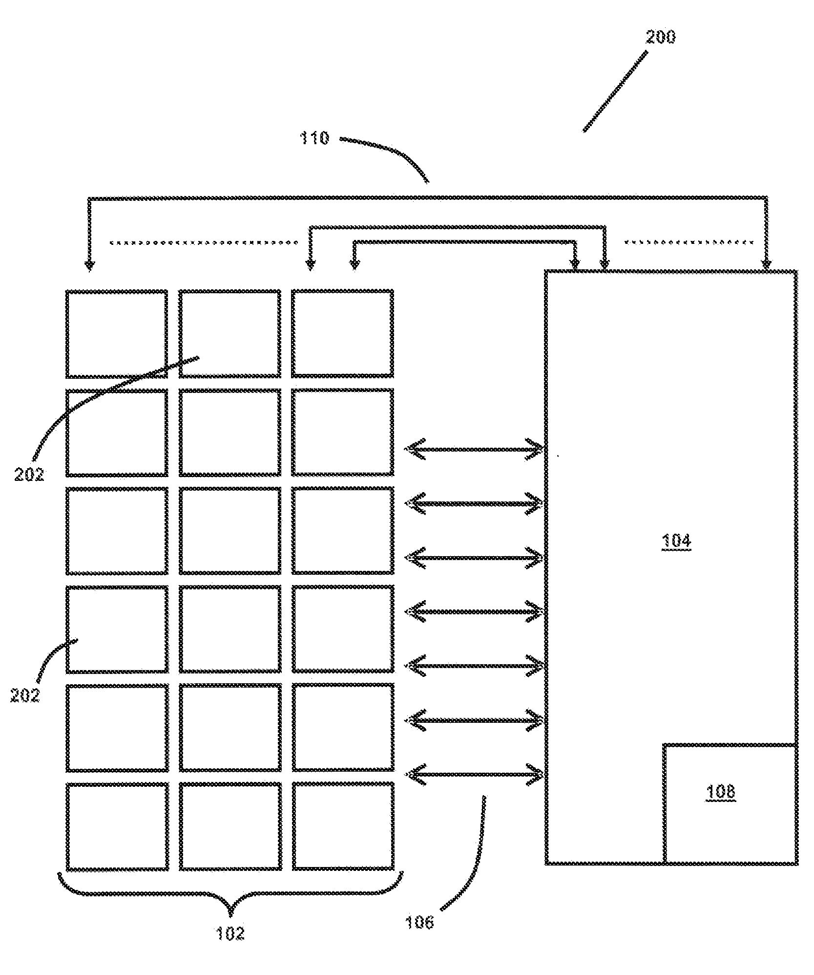
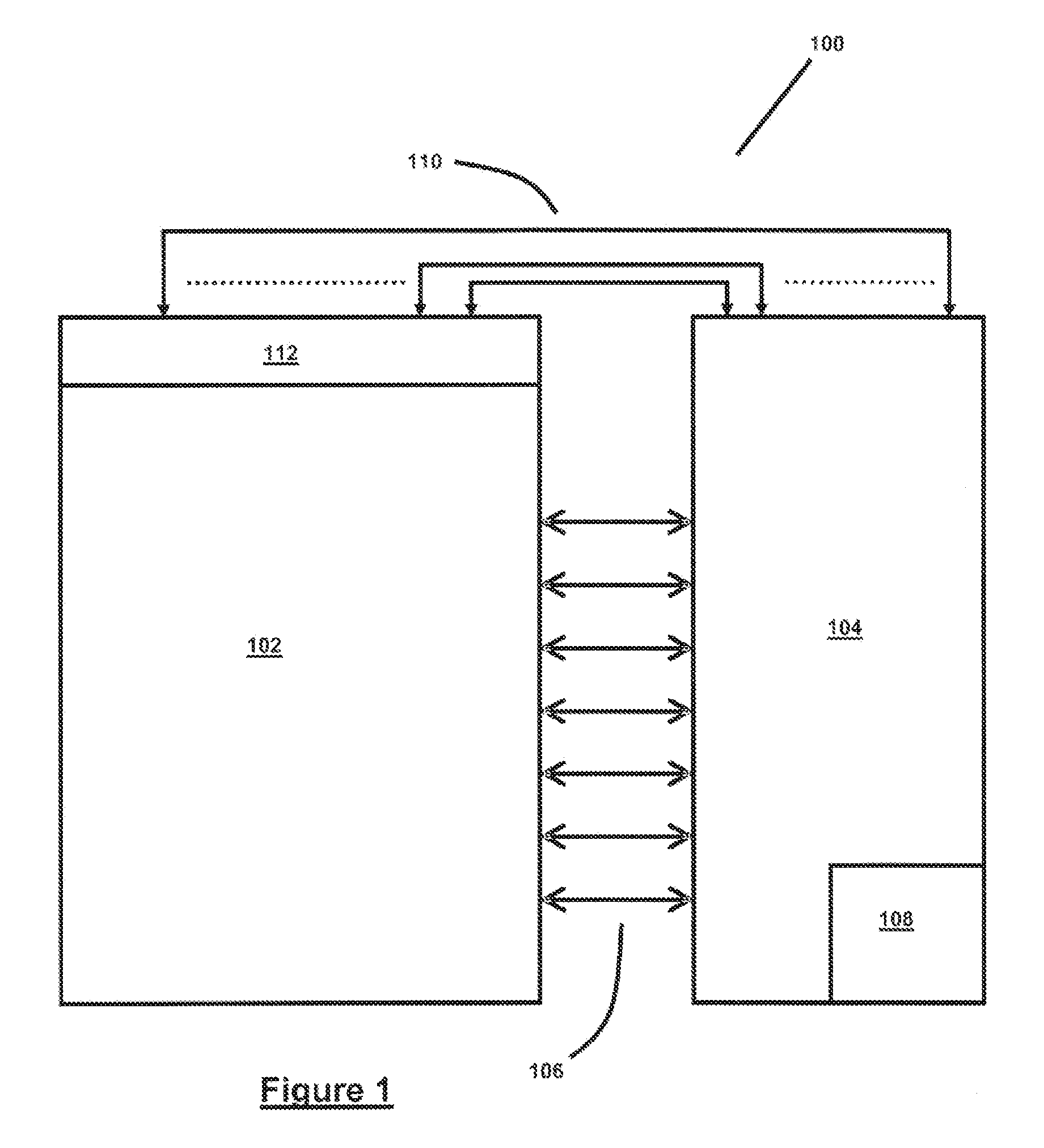
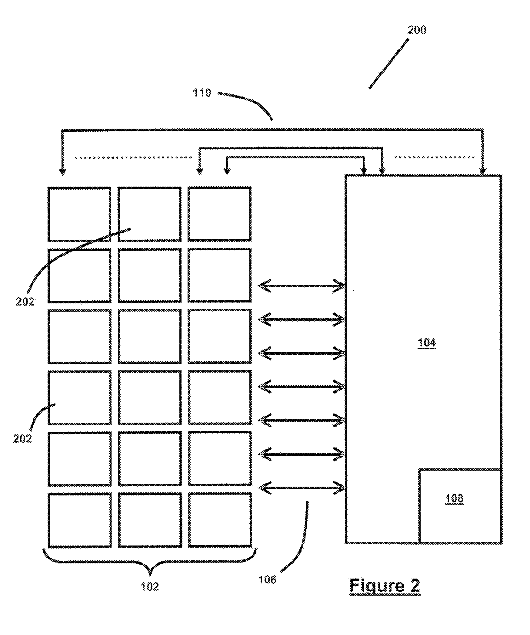
[0066]Referring to FIG. 1, there is provided a flash memory device indicated generally by the reference numeral 100. The flash memory device 100 comprises a flash memory unit 102 and a corresponding controller 104. The controller 104 is used to manage the read, write and / or erase operations on the flash memory unit 102. Algorithms for controlling the flash memory device are stored on the controller 104. The management signals transmitted between the flash memory 102 and the controller 104 are transmitted over a plurality of communications links 106.

[0067]A portion of the controller memory is set aside to act as the operating parameters management unit 108. The operating parameters management unit 108 transmits and receives signals from the flash memory unit 102 over a communications link 110 which may be dedicated or multiplexed. The operating parameters management unit 108 will set the voltage levels and voltage periods required to write to the flash memory unit 102, read from the ...


PUM


Abstract

The present invention is directed to a method for increasing the operational lifetime of a flash memory device, wherein, the method comprises varying the operating parameters of the flash memory device over the lifetime of the flash memory device. The advantage of providing a method which varies the operating parameters of a flash memory device is that the operational lifetime of the flash memory device will be increased. Relatively low voltages and relatively short voltage periods may be used initially to write to, read from and erase the flash cells in the flash memory device. As time passes, the flash cells in the flash memory device will begin to degrade and it will be necessary to increase the voltage and the period of the voltage applied to the flash memory device in order to ensure that the correct write, read and / or erase commands are carried out. The invention is also directed towards a flash memory device.

Description

CROSS REFERENCE TO RELATED APPLICATIONS[0001]The present application claims priority to PCT Application No. PCT / EP2010 / 064086 filed Sep. 23, 2010, which in turn claims priority to Irish Patent Application No. S2009 / 0735 filed Sep. 23, 2009, said applications being incorporated in their entirety herein by reference thereto.FEDERALLY SPONSORED RESEARCH AND DEVELOPMENT[0002]None.BACKGROUND OF THE INVENTION[0003]1. Field of the Invention[0004]This invention relates to a method and apparatus for increasing the operational efficiency of flash memory devices and electronic units that use flash memory devices.[0005]2. Background[0006]Solid-state drives (SSDs) have become increasingly commonplace in many electronic units over the past number of years. The majority of these SSDs use flash memory devices in order to store data.[0007]Flash memory devices typically comprise floating-gate field effect transistors (FETs) as their storage element which may implement NOR flash memory and / or NAND fla...

Claims


Application Information

Patent Timeline
Patent Type & Authority Applications(United States)
IPC IPC(8): G06F12/00
CPCG11C11/5628G11C16/20G06F12/0246G11C16/349G11C16/34
Inventor RYAN, CONOR MAURICESULLIVAN, JOSEPH
Owner RPX CORP
Learn More