Trimmer blade

Inactive Publication Date: 2012-09-27
PANASONIC CORP
View PDF26 Cites 14 Cited by
  • Summary
  • Abstract
  • Description
  • Claims
  • Application Information

AI Technical Summary

Benefits of technology

[0007]It is an object of the present invention to provide a trimmer blade, which can provide good hair inserti

Problems solved by technology

Thus, there is a high possibility that cut surfaces of the many hairs are not flat and uniform.
As a result, this is not preferred as a trimme

Method used


Image

  • Trimmer blade
  • Trimmer blade
  • Trimmer blade

Examples


Embodiment Construction

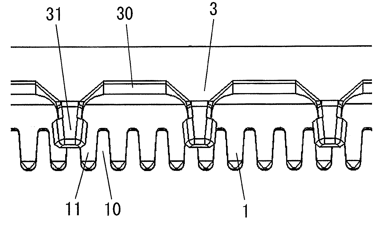
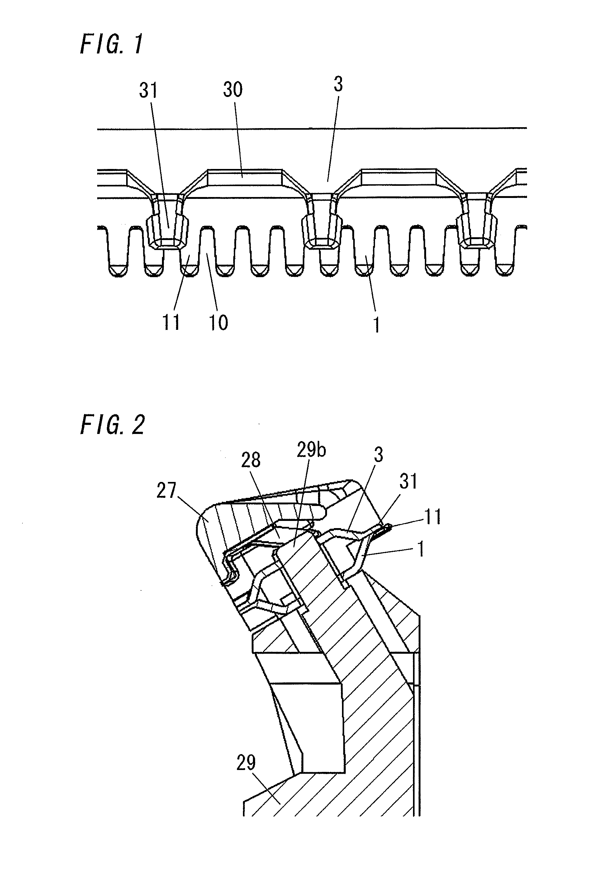
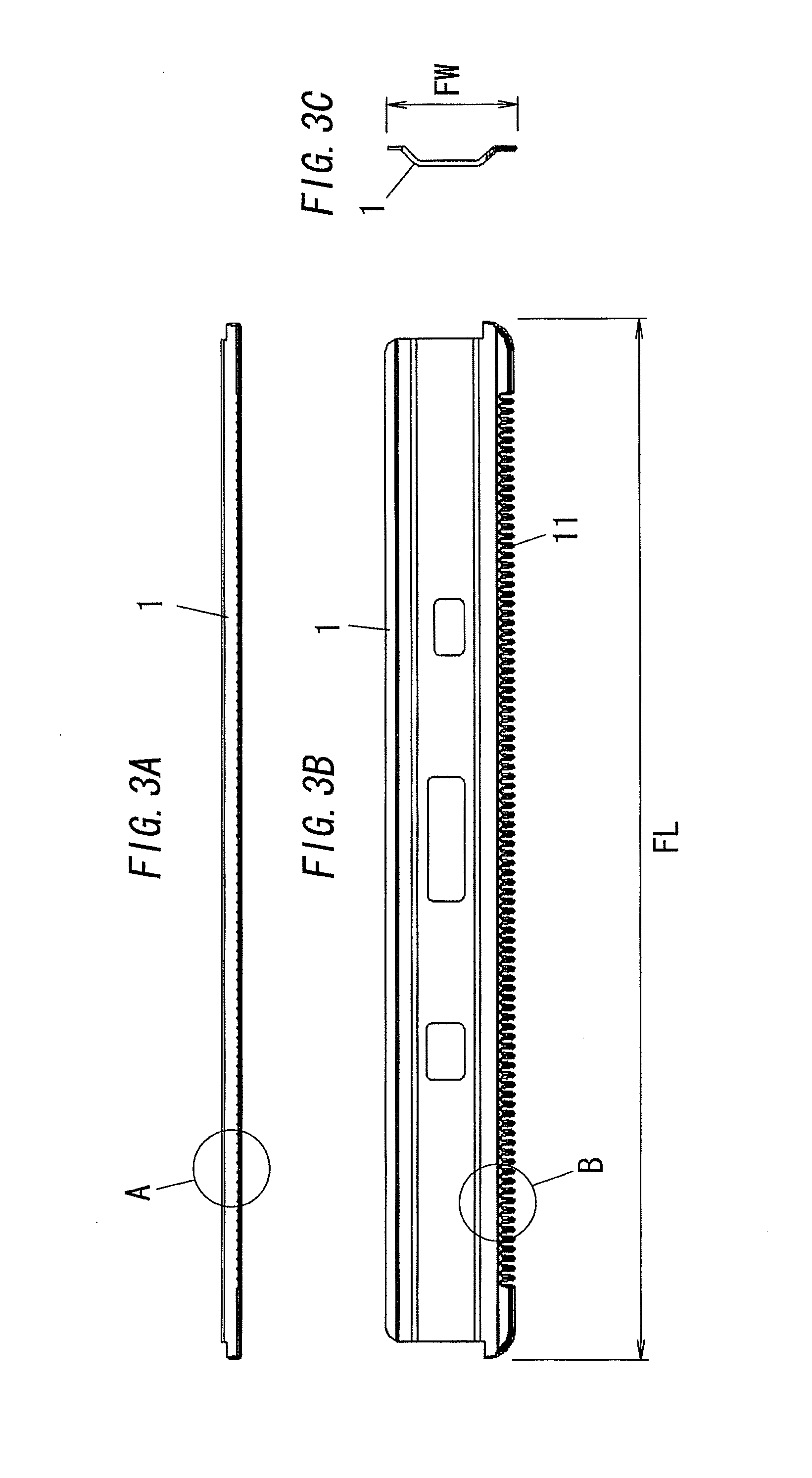
[0033]Hereinafter, an embodiment of the present invention is explained referring to figures. As shown in FIG. 7, a trimmer blade of the embodiment comprises a comb-shaped fixed blade unit 1, a comb-shaped movable blade unit 3, a trimmer base frame 29, a spring member 28 for pressing the movable blade unit 3 to the fixed blade unit 1, and a cover 27.

[0034]The trimmer base frame 29 is a molding product, and is provided in its top face with two bosses 29d, 29d, which are located apart from each other in a longitudinal direction of its top face. A boss 29d has a function to determine the position of the fixed blade unit 1, and to guide the reciprocating movable blade unit 3, and to reduce flexure of the cover 27 when the cover 27 is forced on the trimmer base frame 29. Then, grooves 29c, 29c are formed in both ends of the longitudinal direction of said top face, respectively. These grooves 29c, 29c are formed in order to attach the spring member 28 and the cover 27, and are provided wit...


PUM


Abstract

A trimmer blade comprises a fixed blade unit and a movable blade unit. Then, said fixed blade unit comprises a comb-shaped blade section having a plurality of blades and a plurality of gullets, and said plurality of blades are arranged alternately with said plurality of gullets. Then, said movable blade unit comprises a comb-shaped blade section having a plurality of blades and a plurality of gullets, and said plurality of blades are arranged alternately with said plurality of gullets, and said movable blade unit is configured to slide on said fixed blade unit while reciprocating. A width of each gullet of said movable blade unit is set so that at least two gullets of said fixed blade unit fall inside each gullet of said movable blade unit, as viewed from a direction perpendicular to a sliding surface between said movable blade unit and said fixed blade unit.

Description

BACKGROUND OF THE INVENTION[0001]1. Field of the Invention[0002]The invention relates generally to trimmer blades and, more particularly, to a trimmer blade which comprises a comb-shaped fixed blade unit and a comb-shaped movable blade unit.[0003]2. Description of the Related Art[0004]Generally, a trimmer blade comprises a comb-shaped fixed blade unit and a comb-shaped movable blade unit which is configured to slide on the fixed blade unit while reciprocating. Then, as shown in FIGS. 10A and 10B, the trimmer blade cuts a hair inserted into a gullet 10 of the fixed blade unit by using a blade 11 of the fixed blade unit and a blade 31 of the movable blade unit. In the figures, a sign 4 shows a skin.[0005]Here, in regard to the number of a plurality of blades arranged alternately with a plurality of gullets, the fixed blade unit is typically about the same as the movable blade unit, as shown in Japanese Patent Application Laid-Open No. 2001-096081. However, in such a configuration, man...

Claims


Application Information

Patent Timeline
IPC IPC(8): B26B19/06
CPCB26B19/3846B26B19/06
Inventor INOUE, TOMOYUKISUEYOSHI, HIDEKAZUMURAKI, KENICHI
Owner PANASONIC CORP
Why Eureka
Try Eureka