Cutting Tool

a cutting tool and tool body technology, applied in the field of hand tools, can solve the problems of providing one fixed holding position and unsatisfactory holding effect, and achieve the effects of improving tube positioning effect, simple structure and convenient assembly

Inactive Publication Date: 2012-09-27
ASIAN FIRST REFRIGERATION CORP
View PDF25 Cites 2 Cited by
  • Summary
  • Abstract
  • Description
  • Claims
  • Application Information

AI Technical Summary

Benefits of technology

[0007]An objective of the invention is to provide a cutting tool that has a simpl...

Problems solved by technology

The configuration can only provide one fixed holdi...

Method used


Image

  • Cutting Tool
  • Cutting Tool
  • Cutting Tool

Examples


first embodiment

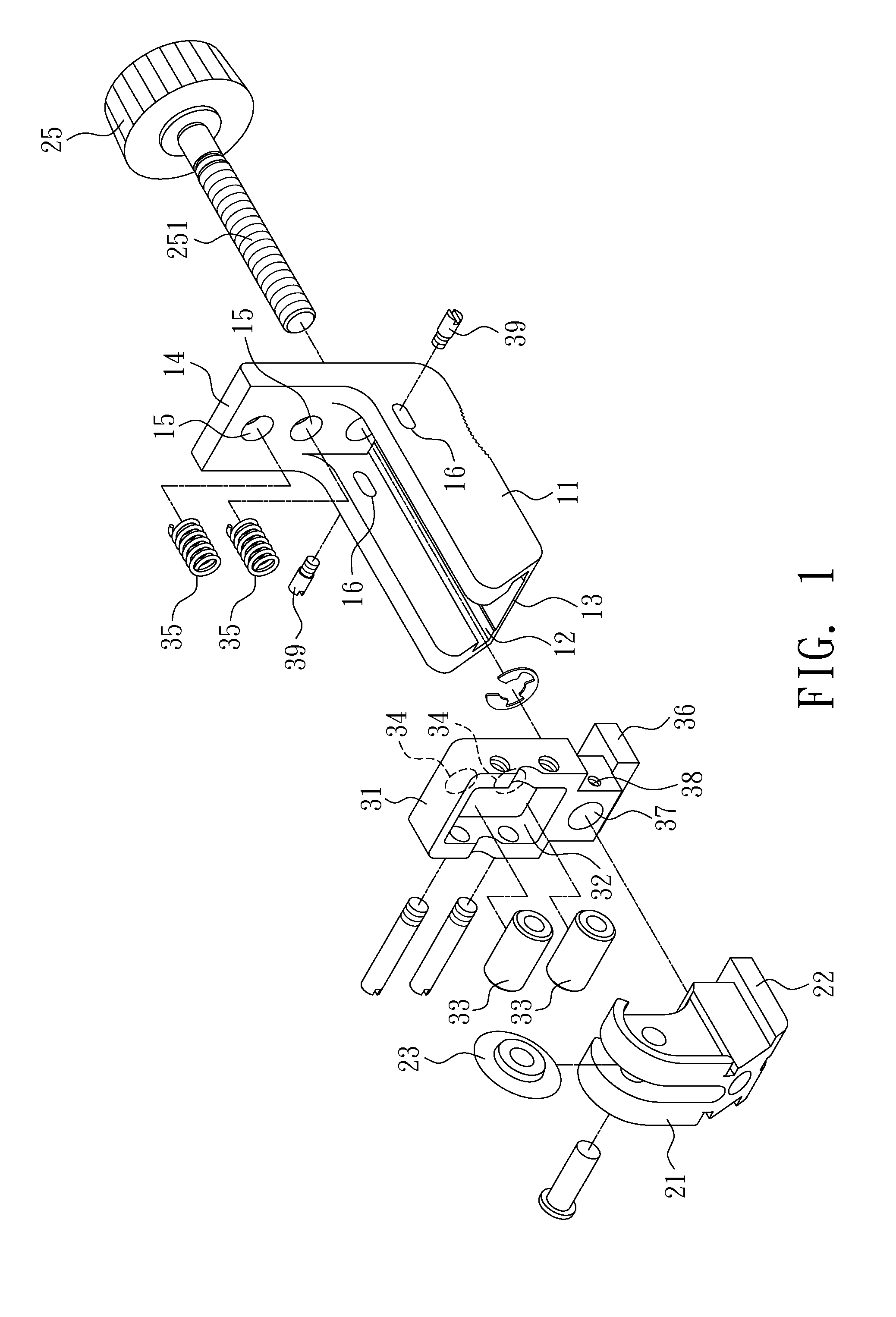
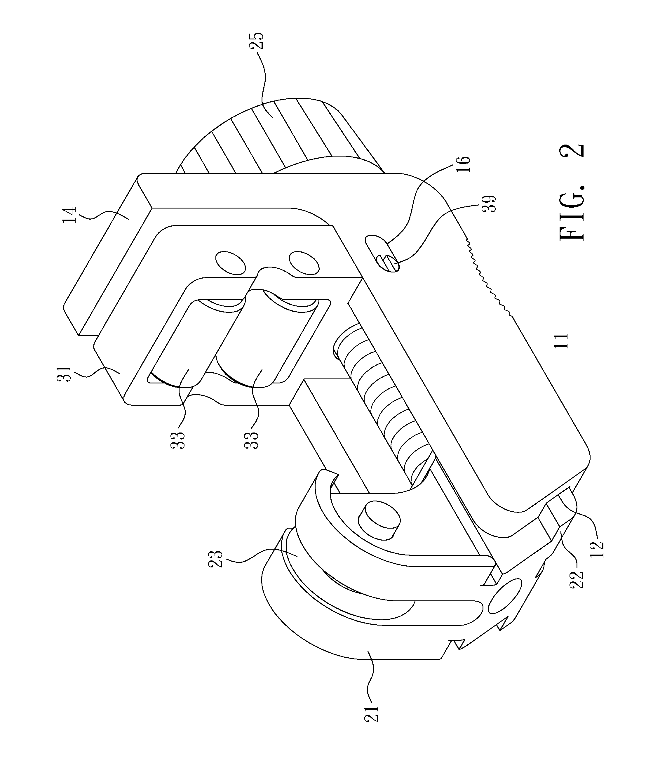
[0023]Please refer to FIGS. Ito 3 for the invention. This invention includes a body 11, a moving base 21, and a roller base 31.

[0024]The bottom of the body 11 has a rail groove 12 extending horizontally. One side of the rail groove 12 is formed with an opening 13 to the outside, while the other side is extended upward with a stopping wall 14. The end surface of the stopping wall 14 toward the rail groove 12 is recessed with two accommodating parts 15. The two sidewalls of the body 11 opposite to the rail groove 12 are formed with a sliding groove 16, respectively.

[0025]The bottom of the moving base 21 is formed with a sliding installation part 22 corresponding to the rail groove 12. The moving base 21 is then installed in a sliding way in the rail groove 12 of the body 11. The top of the moving base 21 is installed with a cutting wheel 23. The moving base 21 has a screw hole 24 in the axial direction of the rail groove 12. A transmission element 25 has an outer thread part 251 corre...
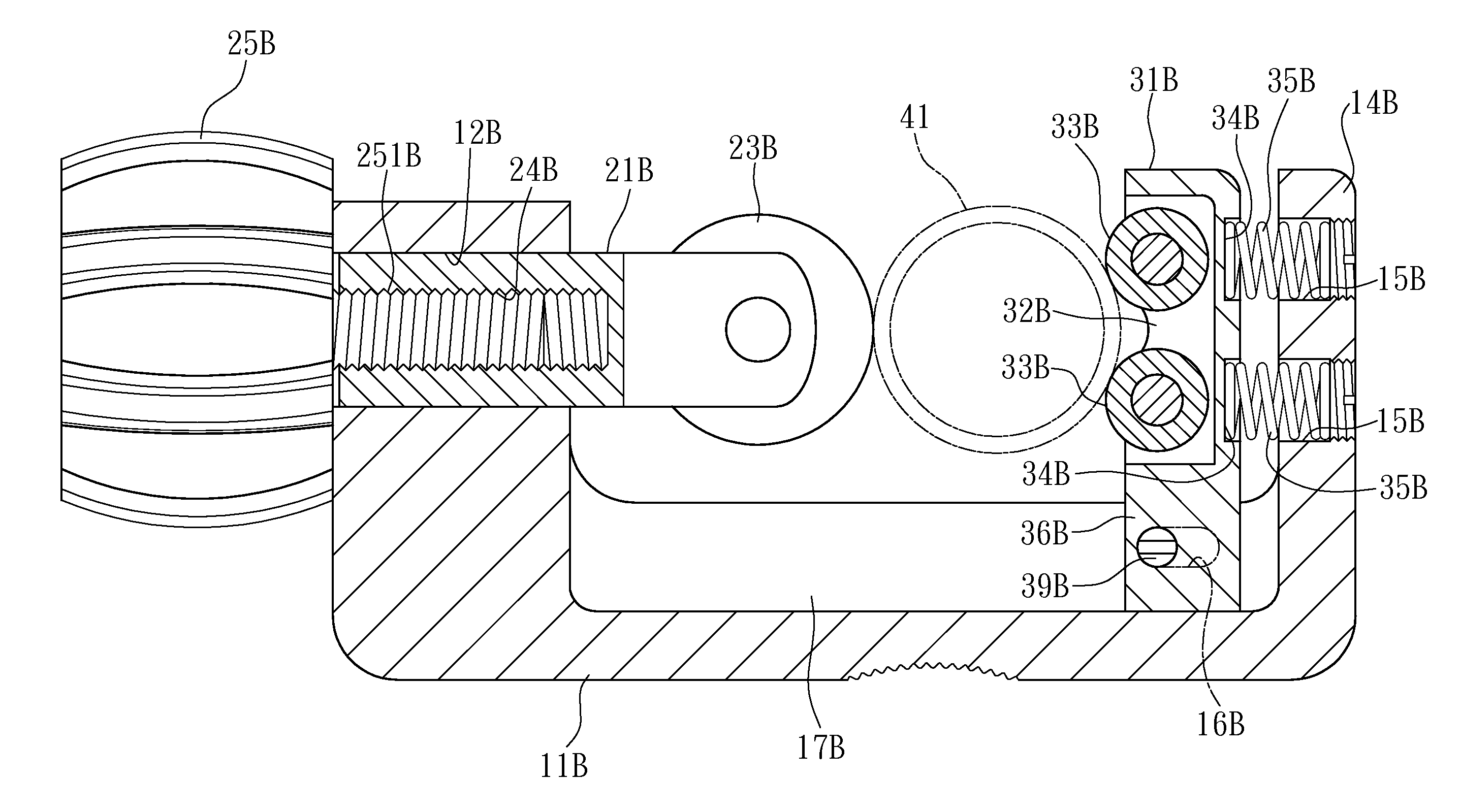
second embodiment

[0033]The second embodiment also uses the elastic elements 35 to urge against the roller base 31B. The roller base 31B thus automatically shifts to the best holding position according to the size of the tube 41, thereby holding it without slipping.


PUM

PropertyMeasurementUnit
Diameteraaaaaaaaaa
Elasticityaaaaaaaaaa

Abstract

A cutting tool includes a body, a moving base, and a roller base. The body has a rail groove, whose one side is extended upward with a stopping wall. The moving base is disposed in the rail groove of the body and has a cutting wheel. The moving base is connected with a transmission element and driven by the transmission element to move along the rail groove. The roller base is interposed between the moving base and the stopping wall. There are a plurality of elastic elements between the roller base and the stopping wall. The roller base is disposed with at least two rollers opposite to the cutting wheel.

Description

CROSS-REFERENCE TO RELATED APPLICATION[0001]This application is a Continuation-In-Part Application of Ser. No. 13 / 072,113, filed on Mar. 25, 2011, and entitled “IMPROVED STRUCTURE OF A CUTTING TOOL”, now pending.BACKGROUND OF THE INVENTION[0002]1. Field of Invention[0003]The invention relates to a hand tool and, in particular, to a cutting tool that can firmly hold a tube.[0004]2. Related Art[0005]FIG. 8 shows the structure of a conventional tube cutter. By turning a knob 51, a rolling cutter 52 moves toward two rollers 53 to hold a tube 54. As one turns the knob 51 with force, the rolling cutter 52 cuts the tube 54.[0006]However, in the conventional tube cutter structure, the rollers 53 are pivotally fixed to one side of the cutter. The configuration can only provide one fixed holding position. It cannot fine-tune according to the size of the tube 54 or the magnitude of exerted force. Therefore, the holding effect is not perfect. If the rolling cutter 52 and the two rollers 53 cann...

Claims


Application Information

Patent Timeline
IPC IPC(8): B23D21/08
CPCB23D21/08
Inventor CHIU, SHENG-CHIH
Owner ASIAN FIRST REFRIGERATION CORP
Why Eureka
Try Eureka