Tool magazine

a tool magazine and tool technology, applied in the field of machine tools, can solve the problems of difficult to ensure precise machining with the tool machine, interference of the exchange of active tools with other tools, and difficulty in precisely positioning the tool magazine on the tool machine, etc., and achieve the effect of providing a lot of spa

Active Publication Date: 2012-09-27
SUN YING
View PDF11 Cites 4 Cited by
  • Summary
  • Abstract
  • Description
  • Claims
  • Application Information

AI Technical Summary

Benefits of technology

[0009]It is the primary objective of the present invention to provide a machine tool with a tool magazine of for carrying a lot of tools and providing a lot of space for exchanging tools.

Problems solved by technology

Where the volume of the tool magazine is made large, the tool magazine is inevitably made bulky and heavy and inevitably becomes a burden for the tool machine so that it is difficult to precisely position the tool magazine on the tool machine.
Therefore, it is difficult to ensure precise machining with the tool machine.
The exchange of the active tool with another tool would be interfered with by adjacent tools.
Hence, the related holders or the spindle would be tilted or deformed, and the operation of the machine tool would be affected.

Method used


Image

  • Tool magazine
  • Tool magazine
  • Tool magazine

Examples


Embodiment Construction

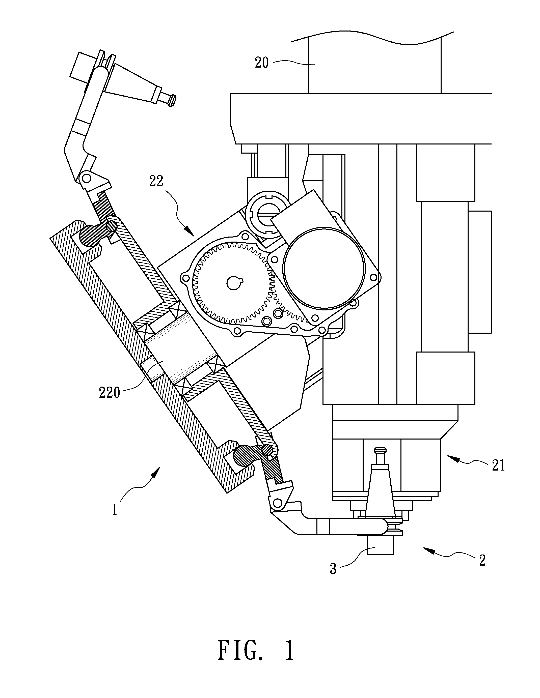
[0018]Referring to FIGS. 1 and 2, a tool machine 2 is equipped with a tool magazine 1 according to the preferred embodiment of the present invention. The tool machine 2 includes a driving unit 20 for driving a spindle 21. Moreover, the tool machine 2 includes a transmission 22 through which the tool magazine 1 is driven by the driving unit 20. The transmission 22 includes an axle 220 formed with a reduced tip. The tool machine 2 will not be further described in detail for being conventional.

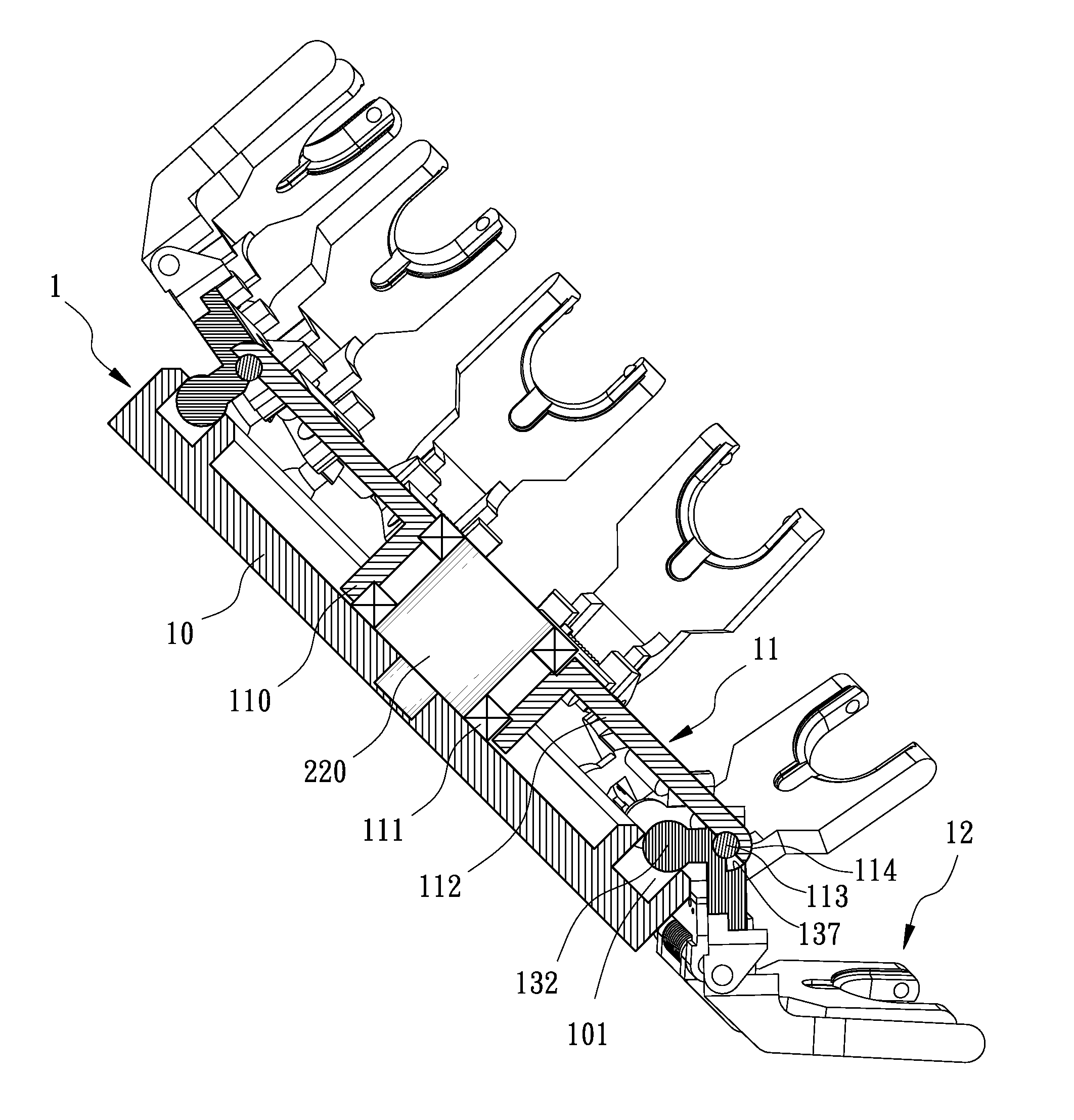
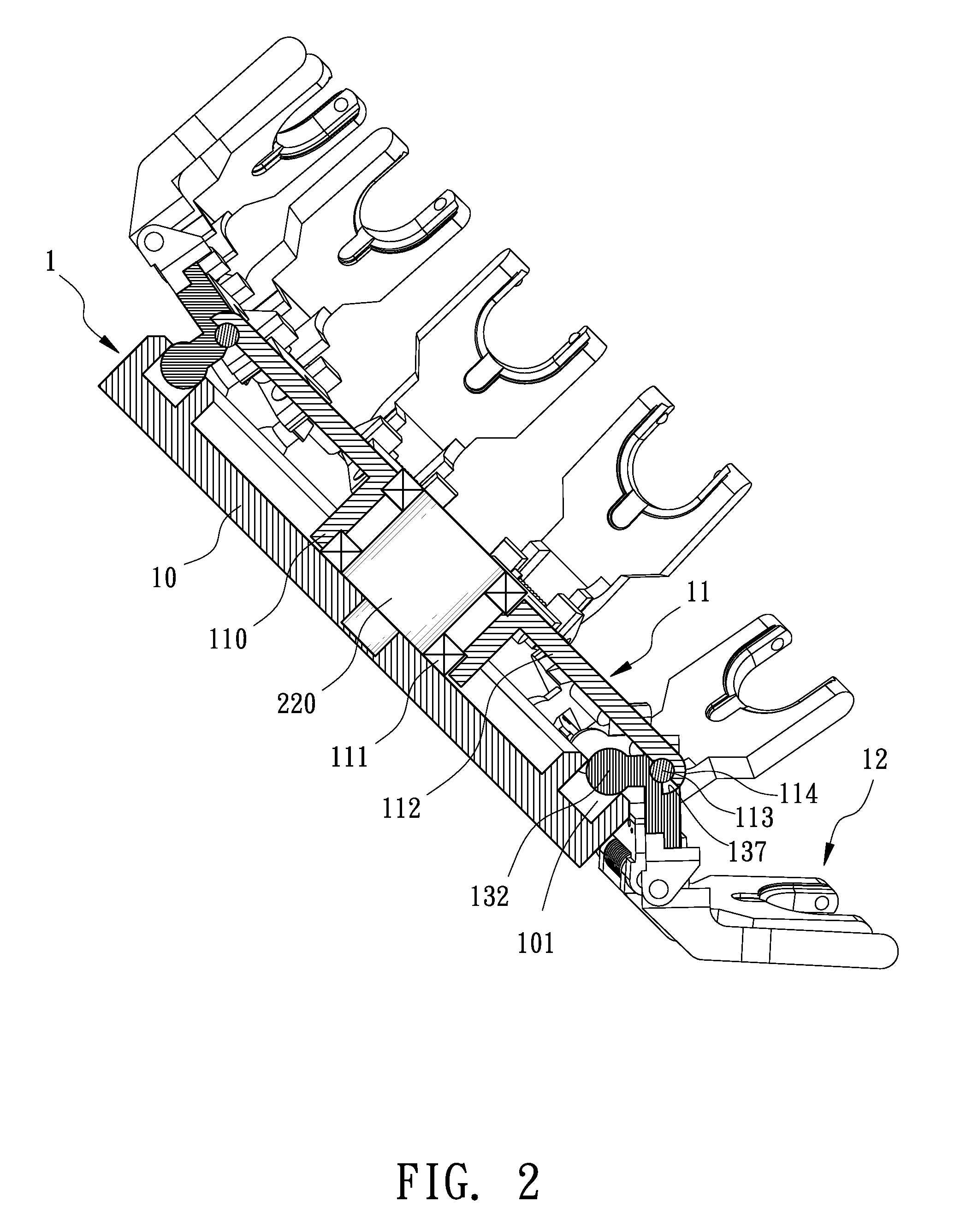
[0019]The tool magazine 1 includes a guiding plate 10, a turntable 11 and holders 12. The guiding plate 1 is non-rotationally connected to the transmission 22. The turntable 11 is rotationally supported on the guiding plate 10 and operatively connected to the transmission 22. The holders 12 are pivotally connected to the turntable 11.

[0020]Referring to FIG. 3 as well as FIGS. 1 and 2, the guiding plate 10 includes an annular ridge 100 formed thereon and an annular groove 101 defined in and along ...


PUM


Abstract

A machine tool is provided with a tool magazine including a guiding plate, a turntable and holders. The guiding plate includes an annular groove with a semi-circular section and a semi-oval section. The semi-circular section is defined by a radius. The semi-oval section is defined by a semi-major axis identical to the radius of the semi-circular section and a semi-minor axis shorter than the semi-major axis. The turntable includes claws extending from the periphery. Each of the holders is pivotally connected to a related one of the claws and includes an end for holding a tool and another end formed with a ball movably located in the annular groove. Thus, some of the holders of which the balls are located in the semi-circular section of the annular groove close while the other holders of which the balls are located in the semi-oval section of the annular groove open.

Description

BACKGROUND OF INVENTION[0001]1. Field of Invention[0002]The present invention relates to a machine tool and, more particularly, to a machine tool equipped with a tool magazine for carrying a lot of tools and providing a lot of space for exchanging tools.[0003]2. Related Prior Art[0004]A tool machine such as a vertical lathe, a milling machine and a machining center includes similar tools with different sizes or different tools of different sizes. The tool machine generally includes a spindle for spinning an active one of the tools, a tool magazine for storing the tools, and a tool exchanger for exchanging the active tool with another tool. There is an on-going trend to store a large number of tools in the tool magazine.[0005]The tool magazine includes holders each for holding a related one of the tools. To store a large number of tools, the volume of the tool magazine is made large or the number of holders is made large.[0006]Where the volume of the tool magazine is made large, the ...

Claims


Application Information

Patent Timeline
Patent Type & Authority Applications(United States)
IPC IPC(8): B65G1/12
CPCY10T483/1795Y10T483/1882B23Q3/15706Y10T483/1836Y10T483/1762Y10T483/1774Y10T483/1873Y10T483/1798B23Q3/15534
Inventor SUN, YING
Owner SUN YING
Why Eureka
Try Eureka