Light Emitting Device Power Supply Circuit, and Light Emitting Device Driver Circuit and Control Method Thereof

Inactive Publication Date: 2012-09-27
RICHTEK TECH
View PDF3 Cites 33 Cited by
  • Summary
  • Abstract
  • Description
  • Claims
  • Application Information

AI Technical Summary

Benefits of technology

[0020]In one embodiment, the light emitting device control circuit preferably includes: a comparator circuit, which compares the detection signal and the rectified dimming signal or a signal related to t

Problems solved by technology

One of the drawbacks of the aforementioned prior art is that the TRIAC dimming circuit 12 includes a TRIAC device, and the TRIAC device requires a large latching current to fire.
However if what th

Method used


Image

  • Light Emitting Device Power Supply Circuit, and Light Emitting Device Driver Circuit and Control Method Thereof
  • Light Emitting Device Power Supply Circuit, and Light Emitting Device Driver Circuit and Control Method Thereof
  • Light Emitting Device Power Supply Circuit, and Light Emitting Device Driver Circuit and Control Method Thereof

Examples


first embodiment

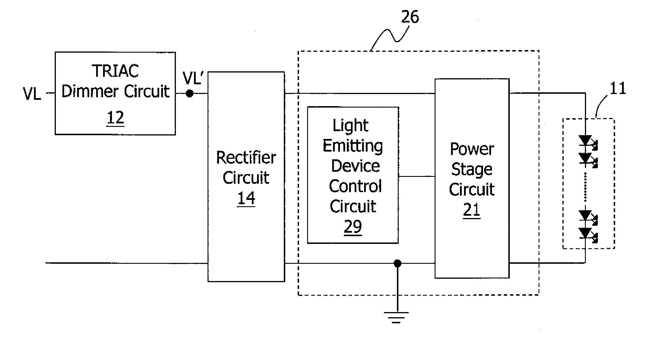
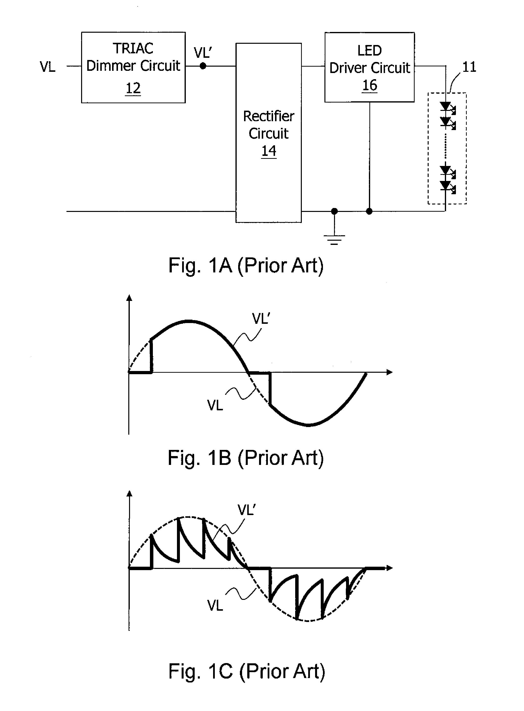
[0035]FIG. 3 shows the present invention. As shown in the figure, a light emitting device power supply circuit includes a tri-electrode AC switch (TRIAC) dimming circuit 12, a rectifier circuit 14, and a light emitting device driver circuit 26. The TRIAC dimming circuit 12 receives an AC signal from the AC input line node VL, having a signal waveform as shown by the dash line in FIG. 4A. When the AC signal exceeds a predetermined trigger phase, the TRIAC dimming circuit 12 fires and turns ON. The TRIAC dimming circuit 12 generates an AC dimming signal at the signal node VL′, having a signal waveform as shown by the solid line in FIG. 4A. The TRIAC dimming circuit 12 includes a TRIAC device, which for example includes two silicon control rectifier (SCR) devices. FIG. 4B shows a symbol of an TRIAC device. The TRIAC device and the SCR device are well known by those skilled in the art, so details thereof are omitted here. In the operation of the TRIAC device, a higher latching current f...

second embodiment

[0042]FIG. 5 shows the present invention. This embodiment shows an example that the light emitting device power supply circuit includes a light emitting device driver circuit 36 which is a non-isolated buck switching regulator. Note that this is only one embodiment of the present invention. The light emitting device driver circuit may be any proper structure. Referring to FIG. 5, the light emitting device driver circuit 36 includes a light emitting device control circuit 39, a power stage circuit 31, and a voltage detection circuit 33. The voltage detection circuit 33 is coupled to the rectifier circuit 14 to detect the rectified dimming signal outputted from the rectifier circuit 14, or its related signal. The voltage detection circuit 33 for example may include a voltage division circuit, which includes resistors R5 and R6 connected in series. One end of the resistor R5 is electrically connected to the rectifier circuit 14, and the voltage division node between the resistors R5 an...

fourth embodiment

[0052]FIG. 9 shows the present invention, which is one specific example embodying the concept shown in FIG. 8. As shown in the figure, the light emitting device control circuit 59 includes a comparator circuit 591, a dimming control circuit 592, and a latch circuit 593. The comparator circuit 591 directly or indirectly compares the detection signal with a dimming reference signal, and generates a trigger signal which is inputted to the latch circuit 593. The detection signal is for example the signal obtained from the pin SEN shown in FIG. 5, and the dimming reference signal is for example the rectified dimming signal obtained from the pin DIM shown in FIG. 5. The dimming control circuit 592 generates a PWM signal according to the rectified dimming signal, wherein the duty ratio of the PWM signal is related to the trigger phase of the rectified dimming signal. (Thus, the comparator circuit 591 indirectly compares the detection signal with the dimming reference signal, because it com...


PUM


Abstract

The present invention discloses a light emitting device power supply circuit, a light emitting device driver circuit and a control method thereof. The light emitting device driver circuit is coupled to a tri-electrode AC switch (TRIAC) dimmer circuit, and it controls the brightness of a light emitting device circuit according a rectified dimming signal. The light emitting device driver circuit includes a power stage circuit and a light emitting device control circuit. The light emitting device control circuit generates a switch control signal. The power stage circuit operates at least one power switch thereof according to the switch control signal to generate a latching current for firing the TRIAC dimmer circuit, and the latching current is inputted to the light emitting device circuit.

Description

CROSS REFERENCE[0001]The present invention claims priority to U.S. provisional application No. 61 / 466,118, filed on Mar. 22, 2011.BACKGROUND OF THE INVENTION[0002]1. Field of Invention[0003]The present invention relates to a light emitting device power supply circuit, a light emitting device driver circuit and a control method thereof. Particularly, it relates to such light emitting device power supply circuit, light emitting device driver circuit and control method thereof which generate a latching current for firing a TRIAC device, wherein latching current is guided to an output node, such that the power utilization efficiency is improved and less flicker occurs.[0004]2. Description of Related Art[0005]FIG. 1A shows a schematic diagram of a prior art light emitting diode (LED) power supply circuit. As shown in FIG. 1A, the LED power supply circuit includes a tri-electrode AC switch (TRIAC) dimming circuit 12, a rectifier circuit 14, and an LED driver circuit 16. The TRIAC dimming ...

Claims


Application Information

Patent Timeline
IPC IPC(8): H05B37/02
CPCH05B33/0815H05B45/3575H05B45/3725H05B45/375
Inventor CHEN, PEI-YUANLIAO, CHIA-WEILIU, JING-MENGHSIU, LENG-NIEN
Owner RICHTEK TECH
Why Eureka
Try Eureka