Filter for improved driver circuit efficiency and method of operation

a filter and driver circuit technology, applied in the field of wireless power, can solve the problems of increasing the amount of power required and consumed by battery-powered electronic devices, increasing the difficulty of recharging, and sometimes inconvenient or cumbersome cable and similar connectors

Active Publication Date: 2012-09-27
QUALCOMM INC
View PDF20 Cites 53 Cited by
  • Summary
  • Abstract
  • Description
  • Claims
  • Application Information

AI Technical Summary

Benefits of technology

[0005]Details of one or more implementations of the subject matter described in this specification are set forth in the accompanying drawings and the description below. Other features, aspects, and advantages will become apparent from the description, the drawings, and the claims. Note that the relative dimensions of the following figures may not be drawn to scale.
[0006]One aspect of the disclosure provides a transmitter device. The transmitter device includes a driver circuit characterized by an efficiency. The driver circuit is electrically connected to a transmit circuit characterized by an impedance. The transmitter device further includes a filter circuit electrically connected to the driver circuit and configured to modify the impedance to maintain the efficiency of the driver circuit at a level that is within 20% of a maximum efficiency of the driver circuit. The impedance is characterized by a complex impedance value. The complex impedance value is within a range defined by a first real impedance value and a second real impedance value. A ratio of the first real impedance value to the second real impedance value is at least two to one.
[0007]Another aspect of the disclosure provides an implementation of a method for filtering a transmit signal. The method includes driving a signal using a driver circuit characterized by an efficiency. The method further includes providing the signal to a transmit circuit characterized by an impedance. The method further includes modifying the impedance to maintain the efficiency of the driver circuit at a level that is within 20% of a maximum efficiency of the driver circuit. The impedance is characterized by a complex impedance value. The complex impedance value is within a range defined by a first real impedance value

Problems solved by technology

While battery technology has improved, battery-powered electronic devices increasingly require and consume greater amounts of power.
As such, t

Method used


Image

  • Filter for improved driver circuit efficiency and method of operation
  • Filter for improved driver circuit efficiency and method of operation
  • Filter for improved driver circuit efficiency and method of operation

Examples


Embodiment Construction

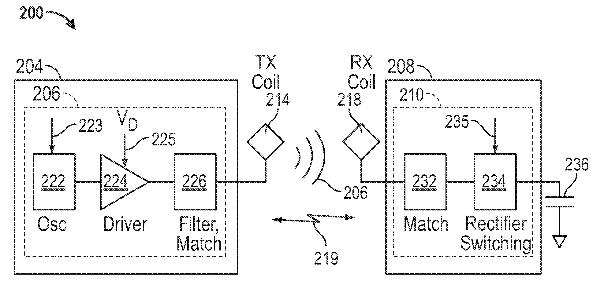
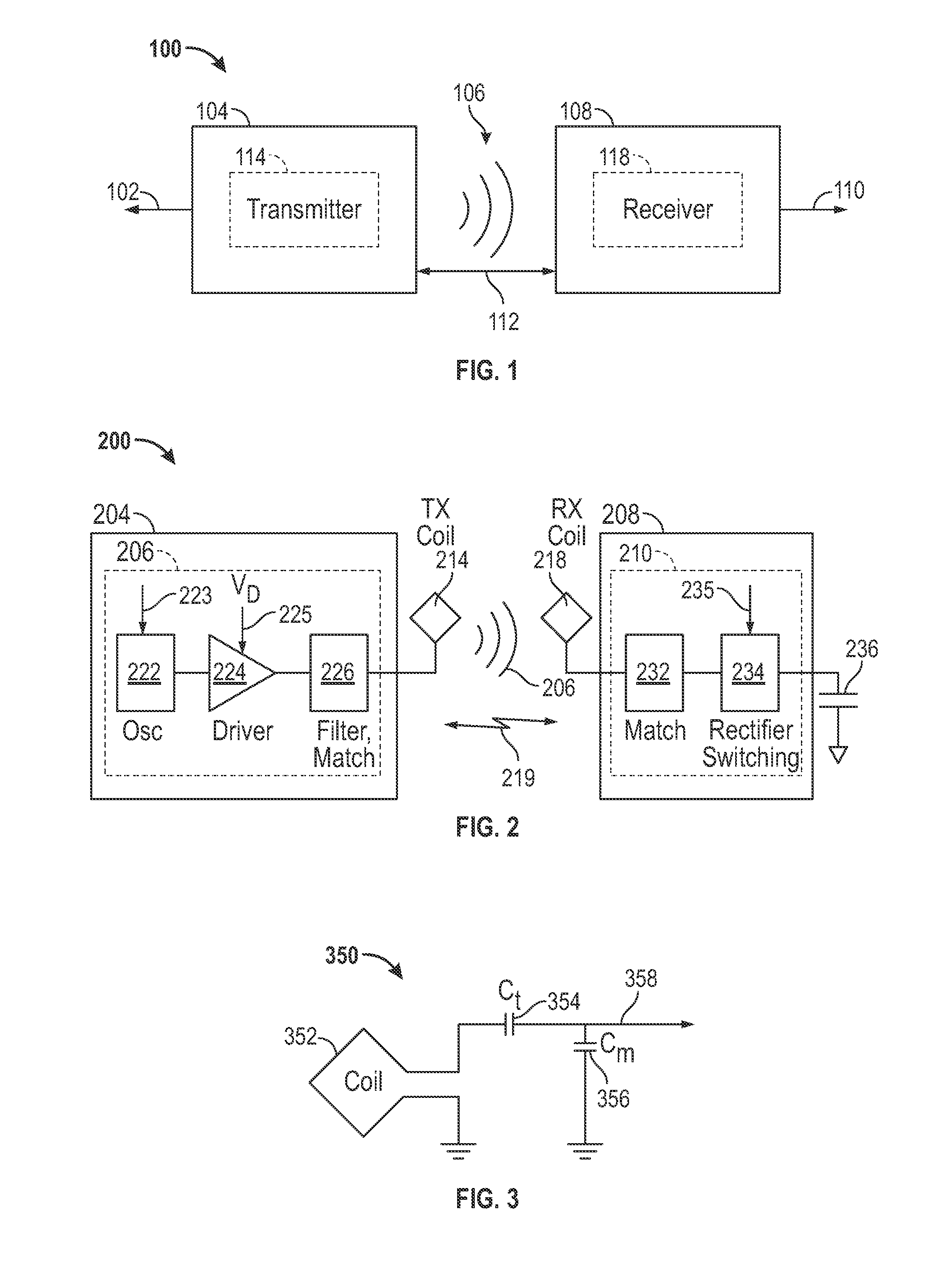
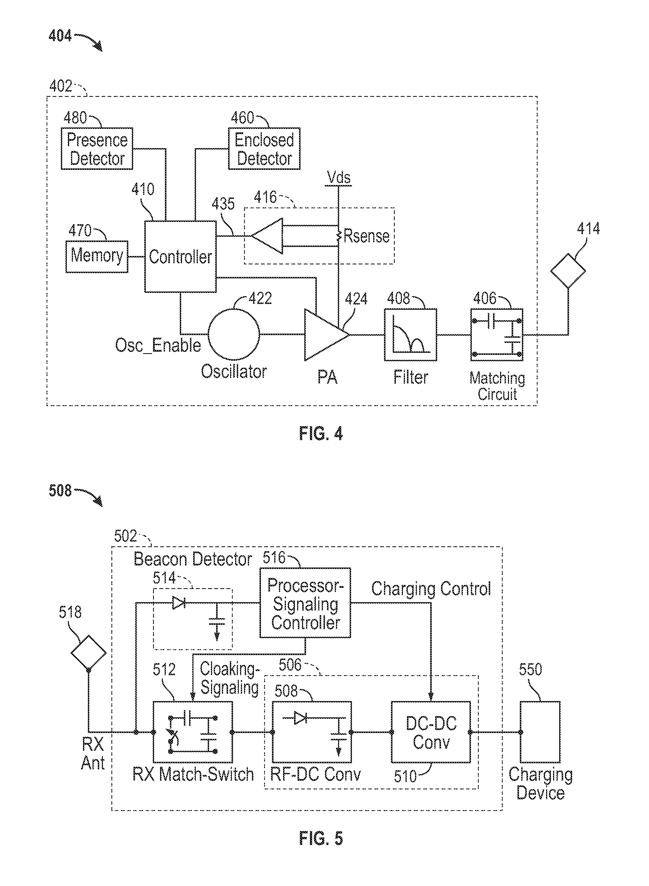
[0034]The detailed description set forth below in connection with the appended drawings is intended as a description of exemplary embodiments of the invention and is not intended to represent the only embodiments in which the invention may be practiced. The term “exemplary” used throughout this description means “serving as an example, instance, or illustration,” and should not necessarily be construed as preferred or advantageous over other exemplary embodiments. The detailed description includes specific details for the purpose of providing a thorough understanding of the exemplary embodiments of the invention. The exemplary embodiments of the invention may be practiced without these specific details. In some instances, well-known structures and devices are shown in block diagram form in order to avoid obscuring the novelty of the exemplary embodiments presented herein.

[0035]Wirelessly transferring power may refer to transferring any form of energy associated with electric fields,...


PUM


Abstract

This disclosure provides systems, methods and apparatus for increasing the efficiency of an amplifier when driven by a variable load. In one aspect a transmitter device is provided. The transmitter device includes a driver circuit characterized by an efficiency. The driver circuit is electrically connected to a transmit circuit characterized by an impedance. The transmitter device further includes a filter circuit electrically connected to the driver circuit and configured to modify the impedance to maintain the efficiency of the driver circuit at a level that is within 20% of a maximum efficiency of the driver circuit. The impedance is characterized by a complex impedance value that is within a range defined by a real first impedance value and a second real impedance value. A ratio of the first real impedance value to the second real impedance value is at least two to one.

Description

CROSS REFERENCE TO RELATED APPLICATIONS[0001]This application claims priority under 35 U.S.C.§119(e) to U.S. Provisional Patent Application No. 61 / 467,853 entitled “CLASS E MATCHING AND HARMONIC LOW PASS FILTER” filed on Mar. 25, 2011, the disclosure of which is hereby incorporated by reference in its entirety. This application further claims priority under 35 U.S.C. §119(e) to U.S. Provisional Patent Application No. 61 / 550,219 entitled “FILTER FOR IMPROVED DRIVER CIRCUIT EFFICIENCY AND METHOD OF OPERATION” filed on Oct. 21, 2011, the disclosure of which is also hereby incorporated by reference in its entirety.FIELD[0002]The present invention relates generally to wireless power. More specifically, the disclosure is directed to improving the efficiency and power output of transmit circuit driving a variable load.BACKGROUND[0003]An increasing number and variety of electronic devices are powered via rechargeable batteries. Such devices include mobile phones, portable music players, lap...

Claims


Application Information

Patent Timeline
IPC IPC(8): H02J7/00H03F3/04H03F3/217H03H7/38
CPCH02J17/00H02J50/12H02J50/40H02J50/60H02J50/70
Inventor WHEATLEY, III, CHARLES EDWARDLOW, ZHEN NINGTONCICH, STANLEY SLAVKONGUYEN, NGO VANWHEELAND, CODY B.
Owner QUALCOMM INC
Why Eureka
Try Eureka