

Elliptically or circularly polarized dielectric block antenna
a dielectric block antenna and elliptical polarization technology, applied in the direction of antennas, electrically short antennas, electrical apparatus, etc., can solve the problems of increasing the size and complexity of the resulting antenna, which is not desirable, and complex structure to manufacture,
- Summary
- Abstract
- Description
- Claims
- Application Information
AI Technical Summary
Benefits of technology
Problems solved by technology
Method used
Image

Examples
first embodiment
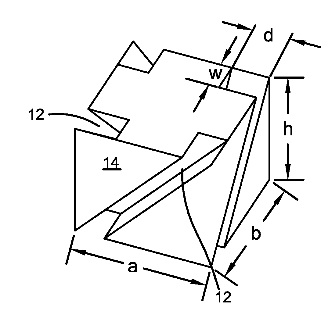
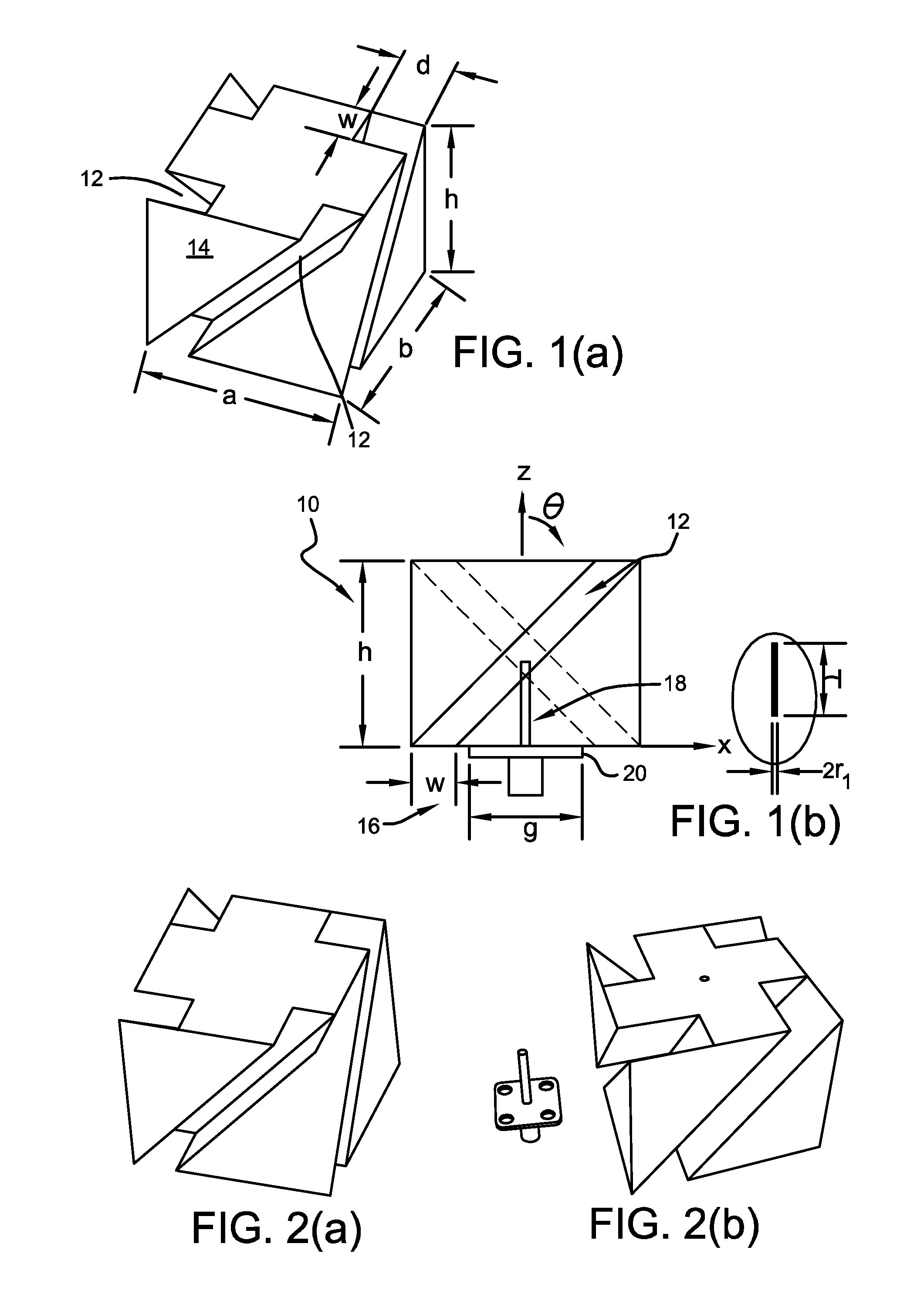
[0056]Referring to FIGS. 1 to 6, there is shown an antenna according to the invention.
[0057]The EP or CP dielectric block antenna 10 comprises a linearly polarized (LP) dielectric block antenna and a wave polarizer directly integrated with said LP dielectric block antenna. The wave polarizer converts the LP wave of the LP dielectric block antenna into an EP or CP wave. The wave polarizer is directly integrated with a component of the LP dielectric block antenna by fabricating inclined slots 12 on faces of the dielectric block 14 at an oblique angle θ to the LP wave direction of polarization (direction z in FIG. 1(b)). This provides a very compact EP or CP antenna 10 with an omnidirectional radiation pattern. The EP or CP antenna 10 is excited by an inner conductor of a SubMiniature version A (SMA) connector 16 that can be directly connected to a coaxial line thereby providing a simple feed network for the antenna. Integrating the wave polarizer with the LP antenna structure simplifi...
second embodiment
[0077]To validate the design of the antenna 10 according to the invention, a wideband omnidirectional LHCP antenna 10 for Worldwide Interoperability for Microwave Access (WIMAX) applications (3.4-3.7 GHz) system was fabricated. The hollow rectangular dielectric block 14 has a dielectric constant of ∈r=15, with dimensions of a=b=37 mm, h=26 mm, a1=10 mm, w=10 mm and d=14.5 mm. The square metallic parasitic patch 34 lying at the top of the dielectric has a side length of p=32.5 mm. The dielectric block 14 is once again centrally fed by a probe 18 of radius r1=0.63 mm and length l=19.6 mm (as better seen in the enlarged portion of FIG. 7(b)). Again, the SMA flange 20 with a side length of g=12.7 mm is used as the small ground plane and no additional ground plane is added or required.
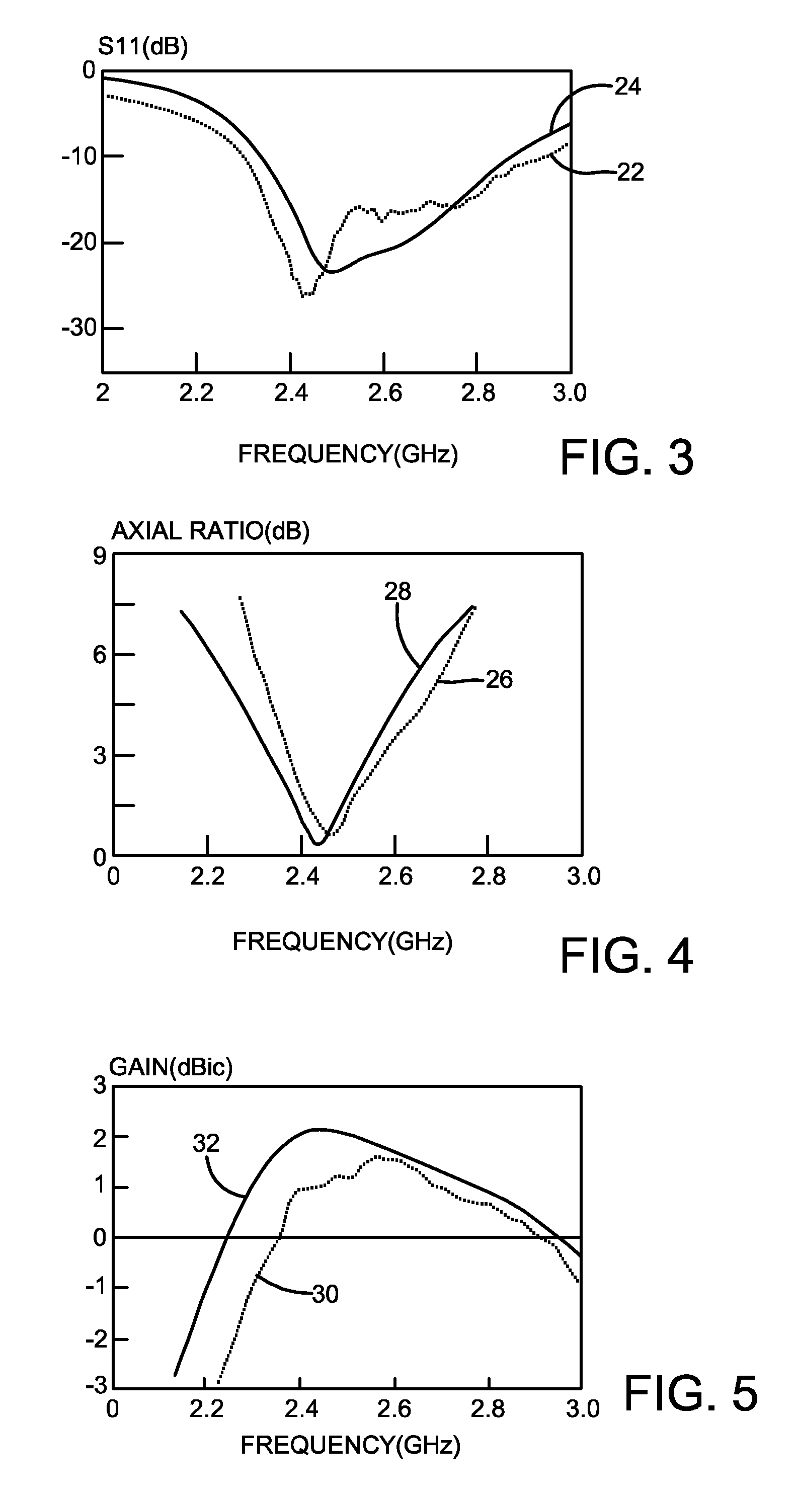
[0078]For this embodiment, FIG. 8 shows the simulated AR of the wideband omnidirectional CP antenna, whereas the inset shows the corresponding reflection coefficient. As can be observed from the figure and ...
third embodiment
[0088]The dielectric constant (∈r) of the dielectric block can be of any value, including ∈r=1 for air or foam material—although ∈r=1 is applicable to the antenna only.
[0089]The dielectric block, slot, metallic patch, and strip can be of any shape.
[0090]The CP antenna of the second and third embodiments can also be LHCP or RHCP and again the same applies to EP antennas.
[0091]The second and third embodiments can also be formed as arrays. In fact, an antenna array may be formed from any combination of antennas according to any of the first, second and third embodiments.
[0092]An omnidirectional EP or CP antenna according to any of the embodiments of the invention can not only suppress the multipath problem caused by signal reflections from building walls, the ground or the like, but also help to stabilize signal transmission and, thus, permit maximum freedom of choice of antenna location. Therefore, such antennas can cover a large service area, which is very attractive for wireless app...
PUM
| Property | Measurement | Unit |
|---|---|---|
| Dielectric polarization enthalpy | aaaaa | aaaaa |
| Angle | aaaaa | aaaaa |
| Area | aaaaa | aaaaa |
Abstract
Description
Claims
Application Information