Guide light device, survey apparatus having the guide light device, survey system using the survey apparatus, survey pole used in the survey system, and mobile wireless transceiver used in the survey system

a technology of guide light and guide light, which is applied in the direction of television system, distance measurement, instruments, etc., can solve the problems of difficulty in finding the guide light and not always being able to find the guide light quickly, and achieve the effect of quick setting operation

Active Publication Date: 2012-09-27
KK TOPCON
View PDF11 Cites 39 Cited by
  • Summary
  • Abstract
  • Description
  • Claims
  • Application Information

AI Technical Summary

Benefits of technology

[0009]An object of the present invention is to provide a guide light device which can quickly perform a setting operation, a survey apparatus having the guide light, a survey system using the survey apparatus, a survey pole used in the survey system, and a mobile wireless transceiver.

Problems solved by technology

However, in the conventional guide light device as mentioned above, the guide light is emitted as a spot light and therefore when the guide light is emitted at a position out of an eye height of the survey operator, it is difficult for the survey operator to find the guide light.
Accordingly, it is not always achieved to find quickly the guide light when the survey operation such as a setting operation is performed at a place which has undulation with difference in height.

Method used


Image

  • Guide light device, survey apparatus having the guide light device, survey system using the survey apparatus, survey pole used in the survey system, and mobile wireless transceiver used in the survey system
  • Guide light device, survey apparatus having the guide light device, survey system using the survey apparatus, survey pole used in the survey system, and mobile wireless transceiver used in the survey system
  • Guide light device, survey apparatus having the guide light device, survey system using the survey apparatus, survey pole used in the survey system, and mobile wireless transceiver used in the survey system

Examples


embodiments

[0037](Configuration of Survey Apparatus)

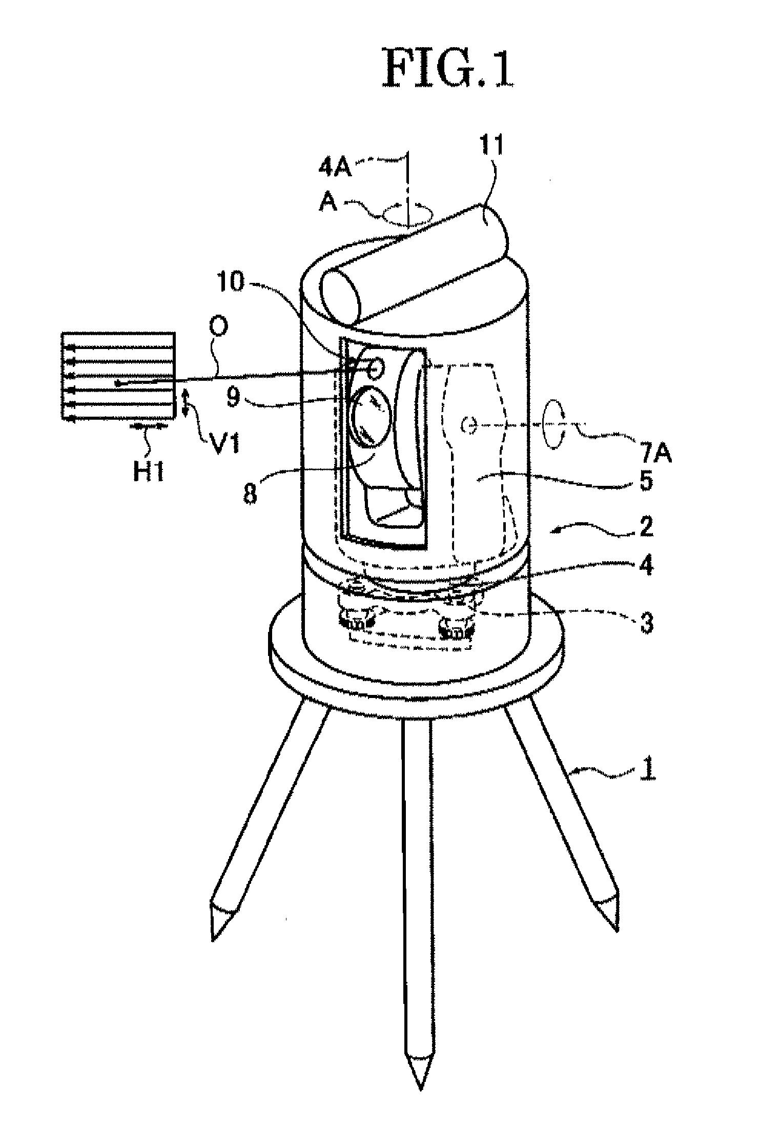
[0038]In FIG. 1, reference numeral 1 indicates a tripod stand and 2 the survey apparatus. The survey apparatus 2 is provided on the tripod stand 1 via a base part 3. The base part 3 has a collimation adjusting screw. The survey apparatus 2 has a mounting part 4.

[0039]The survey apparatus 2 is disposed on a known reference point and design data indicating a positional relationship with setting points is stored in a memory part 50′ of a later-described mobile wireless transceiver 30C (see FIG. 9).

[0040]The mounting part 4 is rotated about a vertical rotational shaft 4A in relation to the base part 3 in a horizontal direction shown by arrow A. On the mounting part 4, a support stand part 5 is provided. On the support stand part 5, a rotation horizontal shaft 7A is provided.

[0041]On the horizontal rotation shaft 7A, a cylindrical part 8 is provided. The cylindrical part 8 is rotated in a horizontal direction by the rotation of the mounting part 4...


PUM


Abstract

A survey apparatus includes a guide light emitting optical system emitting a fan-like visible laser light elongated in upward and downward directions as a guide light, a cylindrical part having a scanning optical system searching a corner reflector provided on a survey pole and a ranging optical system measuring a distance to the corner reflector, a driving part rotating the cylindrical part about a vertical axis in a horizontal direction and rotating the cylindrical part about a horizontal axis, and an angle measurement part measuring a direction of the cylindrical part. The guide light emitting optical system is rotated about the vertical axis in a horizontal direction integrally with the cylindrical part.

Description

CROSS REFERENCE TO RELATED APPLICATIONS[0001]The present application is based on and claims priority from Japanese Application Number, 2011-067629, filed on Mar. 25, 2011, the disclosure of which is hereby incorporated by reference herein in its entirety.BACKGROUND OF THE INVENTION[0002]1. Field of the Invention[0003]The present invention relates to a guide light device, a survey apparatus having the guide light device, a survey system using the survey apparatus, a survey pole used in the survey system, and a mobile wireless transceiver used in the survey system.[0004]2. Description of the Related Art[0005]In a survey apparatus performing a measurement of a distance and an angle, a conventional guide light device which emits a guide light to indicate a collimation direction of the survey apparatus to a survey operator has been known (see Japanese Utility model application publication No H05-28925).[0006]In such a survey apparatus, light emitting diodes which have different colors an...

Claims


Application Information

Patent Timeline
Patent Type & Authority Applications(United States)
IPC IPC(8): G01C3/08H04N7/18
CPCG01C15/004G01C15/002G01C15/02G01S17/42G01S17/48
Inventor KUMAGAI, KAORUCHIBA, MINORU
Owner KK TOPCON
Why Eureka
Try Eureka