Optical testing apparatus and methods

a technology of optical testing and optical surfaces, applied in the field of optical systems, can solve the problems of prohibitive price, lack of degree of freedom to adequately measure,

Active Publication Date: 2012-09-27
UNIVERSITY OF ROCHESTER
View PDF2 Cites 5 Cited by
  • Summary
  • Abstract
  • Description
  • Claims
  • Application Information

AI Technical Summary

Benefits of technology

[0034]An embodiment of the invention is an apparatus and associated method for testing a phi-polynomial surface with a conventional, commercially available Fizeau or Twyman-Green type interferometer. The apparatus uses several simple (singlet) optical elements in an Offner null configuration in addition to an active optical element (e.g., actuated, deformable membrane) to create an asymmetric reference wavefront that allows for conventional null-based or quasi-null-based interferometry.

Problems solved by technology

A CGH reference is accurate within a reasonable range of magnification, but the pricing is prohibitive in many cases, especially if the optical system contains three or more optical surfaces where a separate CGH null is required for each optical surface.
In each case, the adaptive null is rotationally symmetric and does not provide the degrees of freedom to adequately measure a non-rotationally symmetric optical surface like a phi-polynomial surface.

Method used


Image

  • Optical testing apparatus and methods
  • Optical testing apparatus and methods
  • Optical testing apparatus and methods

Examples


Embodiment Construction

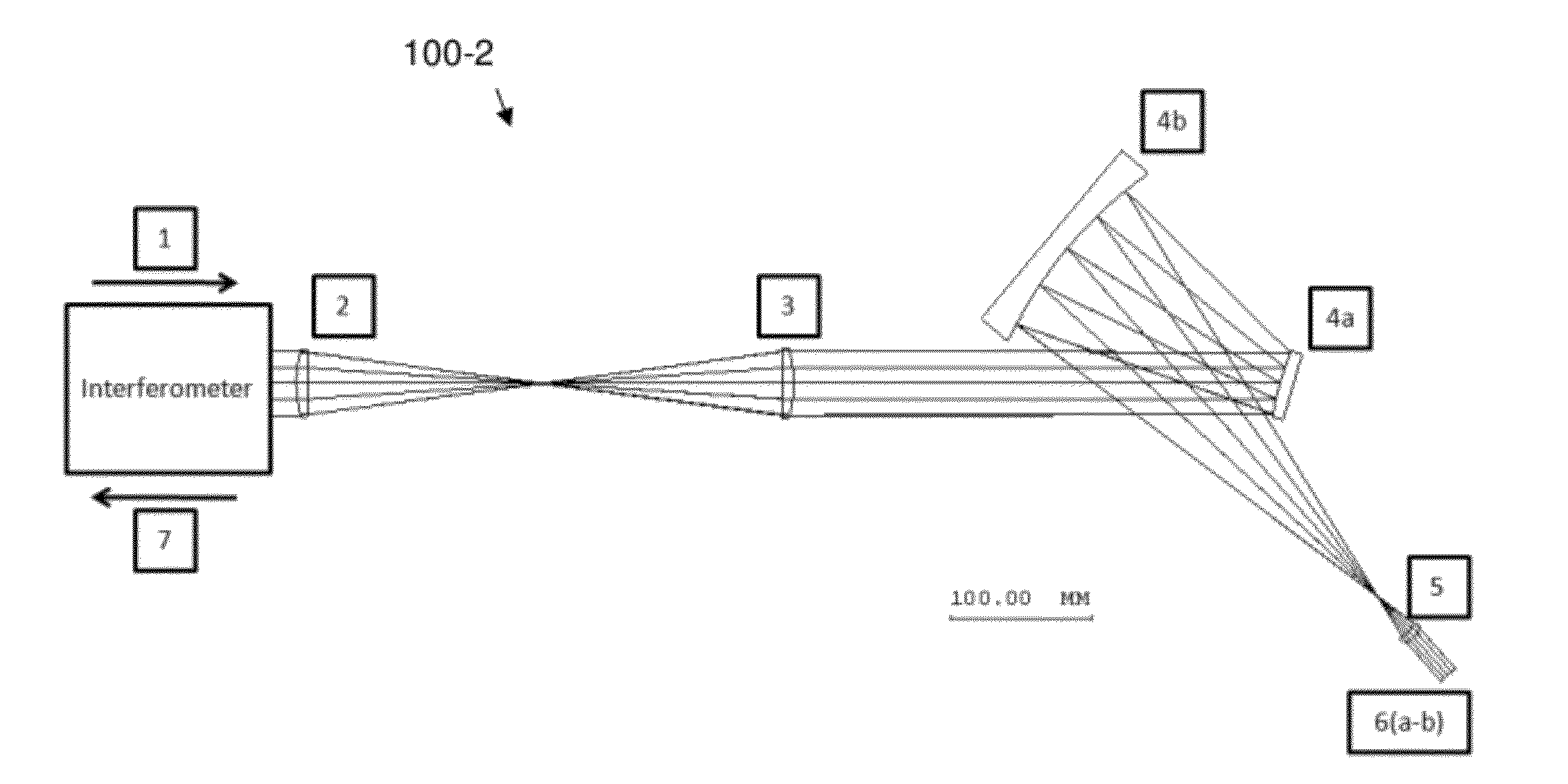
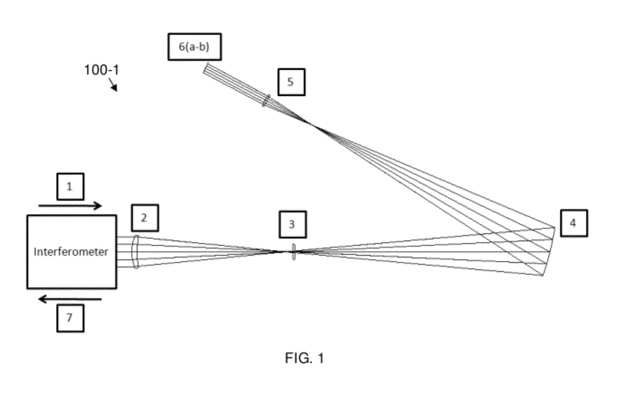
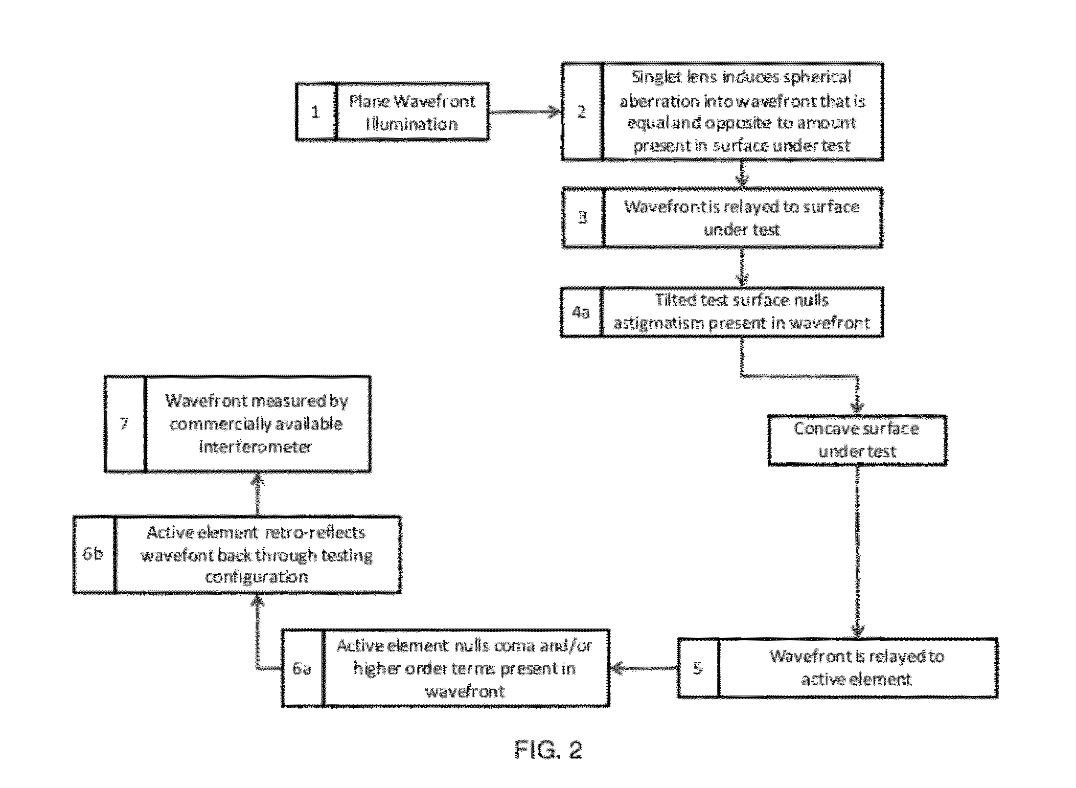
[0042]Reference will now be made in detail to the present exemplary embodiments of the invention, examples of which are illustrated in the accompanying drawings.

[0043]A φ-polynomial surface takes the form:

z=F(ρ,φ),  (1)

where the sag, z, is represented by some function that depends on the radial component, ρ, and the azimuthal component, φ. With the sag of the optical surface taking this form, the surface is no longer limited to being rotationally symmetric as is the case when the sag only depends on the radial component, that is, z=F(ρ). Moreover, with this additional degree of freedom the surface can correct for asymmetric aberrations (i.e. coma) within an optical design.

[0044]According to an illustrative, non-limiting example for demonstrating the embodied invention, the φ-polynomial surface type that is used is a Zernike polynomial surface described by the following equation:

z=cρ21+1-(1+k)c2p2+∑j=116CjZj,(2)

where z is the sag of the surface, c is the vertex curvature, k is the co...


PUM


Abstract

An apparatus and associated method for testing a non-symmetric (e.g., phi-polynomial) surface. The apparatus uses several simple (singlet) optical elements (e.g., an Offner null configuration) and a tilted optic under test in combination with an active optical element (e.g., actuated, deformable membrane mirror, optical phase modulator, etc.) that together form a null or quasi-null that allows for conventional null-based interferometry. This solution solves the problem of exceeding the dynamic range of a conventional interferometer when trying to test non-symmetric optical surfaces.

Description

RELATED APPLICATION DATA[0001]The instant application claims priority to U.S. Provisional application Ser. No. 61 / 546,230 filed on Oct. 12, 2011 and U.S. Provisional application Ser. No. 61 / 467,075 filed on Mar. 24, 2011, the subject matters of which are incorporated herein by reference in their entireties.GOVERNMENT FUNDING[0002]This invention was made with support from the National Science Foundation under Agreement No. ECCS-1002179. The government has certain rights in the invention.BACKGROUND[0003]1. Field of the Invention[0004]Embodiments of the invention are generally directed to the field of optical systems; more particularly, to an optical surface metrology apparatus and associated method; and, most particularly an optical surface metrology apparatus and associated method for use with a phi (φ)-polynomial surface.[0005]2. Related Art Discussion[0006]Interferometric measuring apparatuses are commonplace in the optical fabrication industry and provide the fabricator with a sur...

Claims


Application Information

Patent Timeline
Patent Type & Authority Applications(United States)
IPC IPC(8): G01B11/24
CPCG01M11/025G01M11/005
Inventor ROLLAND, JANNICK P.FUERSCHBACH, KYLE
Owner UNIVERSITY OF ROCHESTER
Why Eureka
Try Eureka