System for testing optical axis of broadband multi-sensor electro-optic apparatus

A multi-sensor and photoelectric instrument technology, applied in the field of optical systems, can solve the problem that the mechanical reference axis of the instrument installation cannot be completely consistent.

Inactive Publication Date: 2007-08-01
CHANGCHUN INST OF OPTICS FINE MECHANICS & PHYSICS CHINESE ACAD OF SCI
View PDF0 Cites 27 Cited by
  • Summary
  • Abstract
  • Description
  • Claims
  • Application Information

AI Technical Summary

Problems solved by technology

[0003] In order to solve the problem that the optical axis of each optical sub-system of a large-scale photoelectric instrument cannot be completely consistent, and the optical axis of each optical sub-system and the mechanical reference axis of the entire instrument install...

Method used


Image

  • System for testing optical axis of broadband multi-sensor electro-optic apparatus

Examples


Embodiment Construction

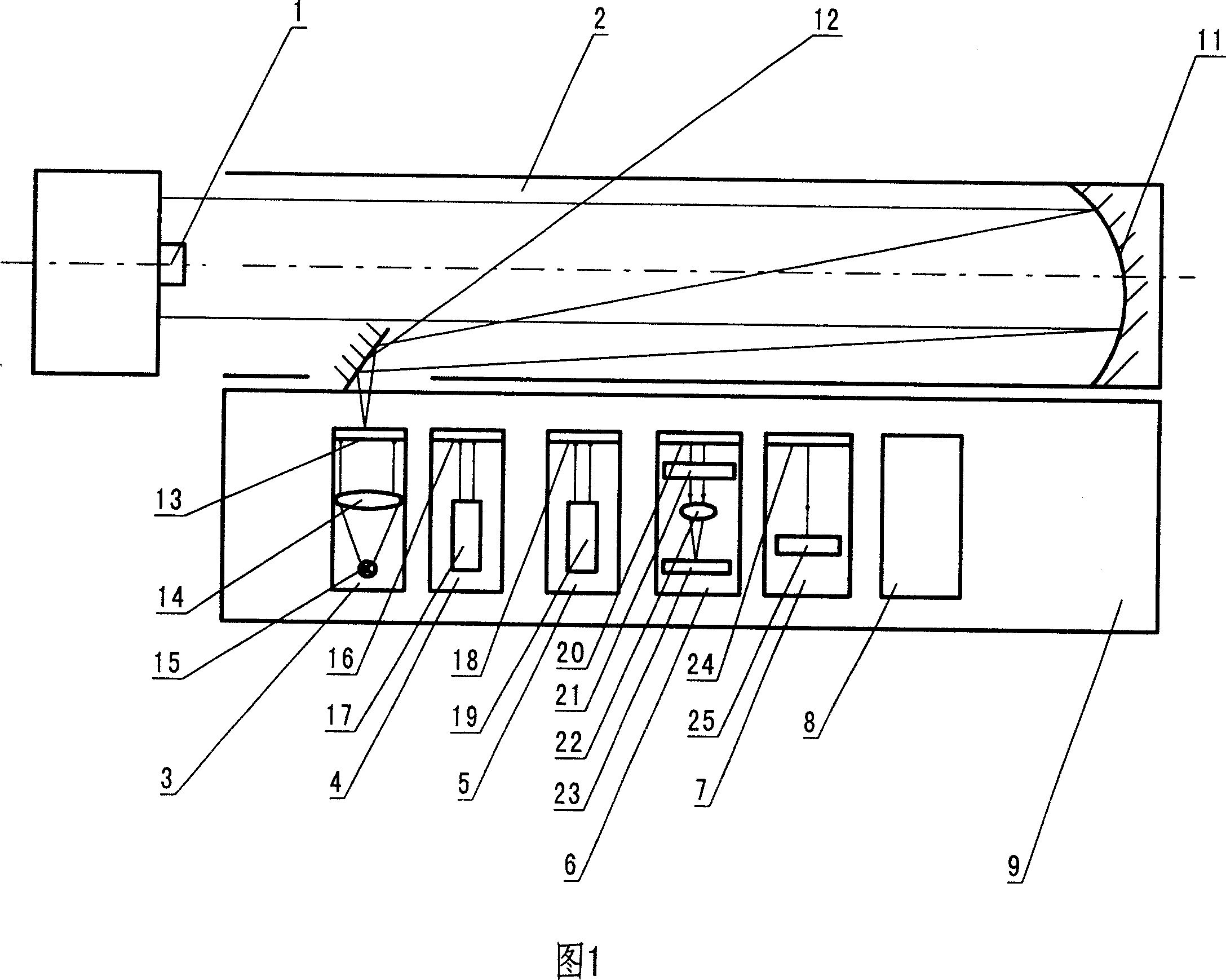
[0007] The reference plane mirror 1 adopts a high-quality plane mirror.

[0008] The collimator 2 adopts a reflective collimator, and its main mirror is an off-axis parabolic reflector 10, and a plane reflector 11 is added near the image plane of the off-axis parabolic reflector 10 to refract the convergent focus of the off-axis parabolic reflector 10. Turning to the image plane, the image plane is parallel to the optical axis of the collimator 2, so as to eliminate stray light interference. The size of the off-axis parabolic reflector 10 is φ400mm and focal length f=4000mm.

[0009] Visible light self-collimating aiming optical system 3 is made up of first target board 12, condenser lens 13, halogen lamp 14; axis, the first target plate 12 can be a cross-hair plate or a star point orifice plate, etc.

[0010] The far-infrared optical system 4 is composed of a second target plate 15 and a 9-13 μm blackbody light pipe 16 , and the optical axis of the 9-13 μm blackbody light p...


PUM


Abstract

This invention relates to one wide band multi-sensor device light axis test system in optical test technique, which comprises the following steps: fixing the devices with different wave lengths into guide rail and moving their focus parts onto parallel focus surface through adjusting system in cross or star holes; receiving laser spot CCD receive system parts; using parallel light tube to make cross or star point hole onto tested system each optical display to receive test system laser.

Description

technical field [0001] The invention belongs to the technical field of optical detection, and relates to a line of sight (optical axis) for a plurality of optical sub-systems of a photoelectric tracking instrument that transmits light waves of different bands, and the consistency (parallelism or angular deviation) between the mechanical reference axes of the entire instrument installation. ) Optical system for detection and calibration. Background technique [0002] At present, large-scale optoelectronic instruments are composed of multiple optical subsystems. Each optical subsystem transmits light waves of different bands, and uses different sensors to receive the light waves of the transmitted bands. The entire optoelectronic instrument has its own installation mechanical reference axis, and each optical subsystem also has its own optical axis. Due to the influence of various factors in the design dimensions, machining accuracy and assembly process of each component, the ...

Claims


Application Information

Patent Timeline
IPC IPC(8): G01B11/26G01M11/00
Inventor 周兴义马军
Owner CHANGCHUN INST OF OPTICS FINE MECHANICS & PHYSICS CHINESE ACAD OF SCI
Why Eureka
Try Eureka