Optical module testing system

a technology of optical modules and testing systems, applied in the direction of optical elements, optical apparatus testing, instruments, etc., can solve the problems of inefficient serial assembly and testing, inefficient devoted production lines or testing stations to a particular module or component, and inability to meet the needs of electronic equipment manufacturers

Inactive Publication Date: 2004-01-13
CIENA
View PDF6 Cites 29 Cited by
  • Summary
  • Abstract
  • Description
  • Claims
  • Application Information

AI Technical Summary

Problems solved by technology

Optical networking equipment manufacturing presents difficult challenges not faced by electronic equipment manufacturers.
Furthermore, the orders are often unpredictable and sporadic which means that the manufacturing must be highly adaptable and dynamic.
Thus, it is inefficient to dedicate a production line or testing station to a particular module or component.
Such serial assembly and testing is inefficient and labor intensive.
As such, the typical test station is not flexible and leads to inefficient utilization of test equipment and labor resources.
Furthermore, the high mix environment faced by optical networking equipment manufacturers makes using a parallel testing architecture inadequate since different tests needs to be performed on the high mix of components.

Method used


Image

  • Optical module testing system
  • Optical module testing system
  • Optical module testing system

Examples


Embodiment Construction

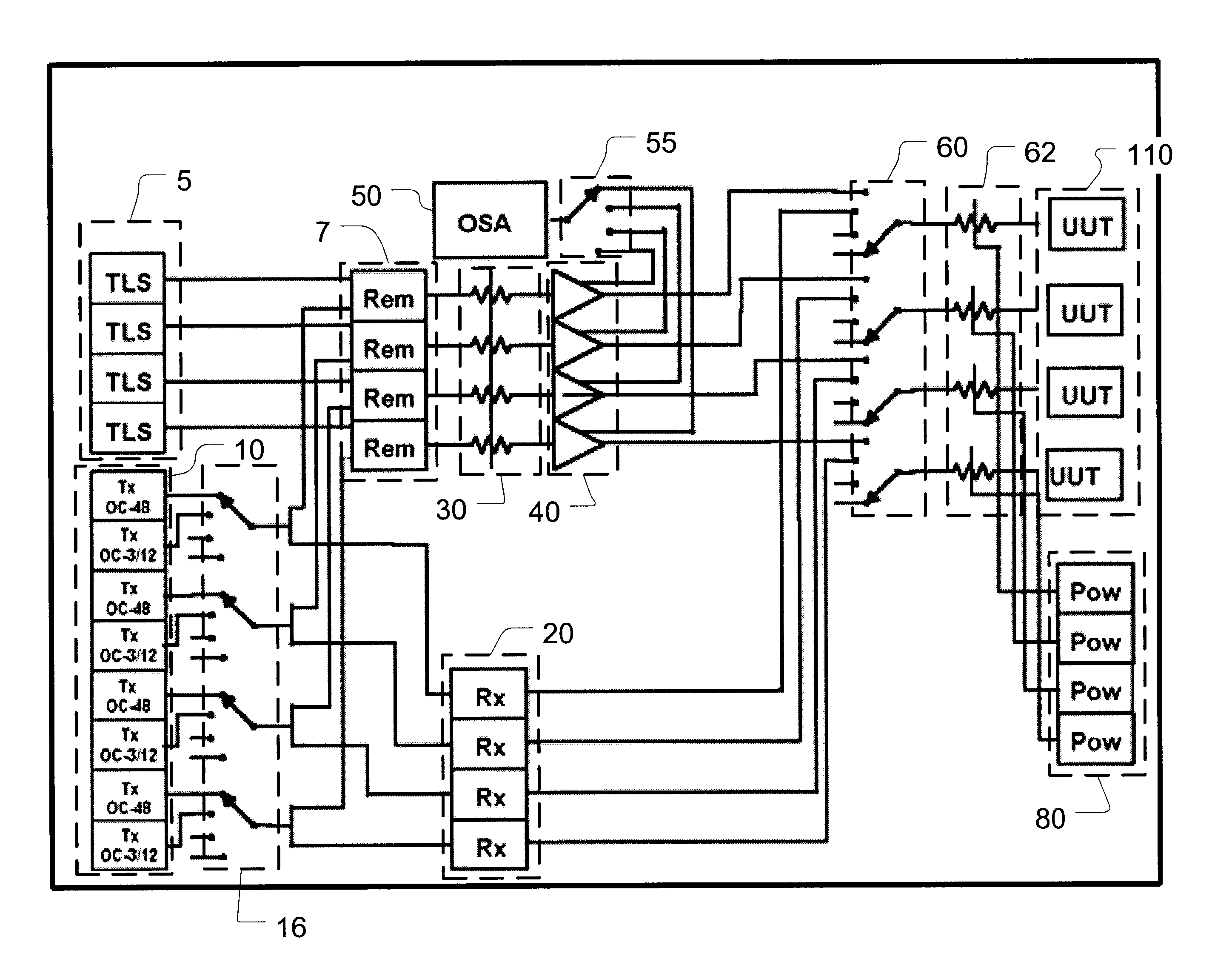
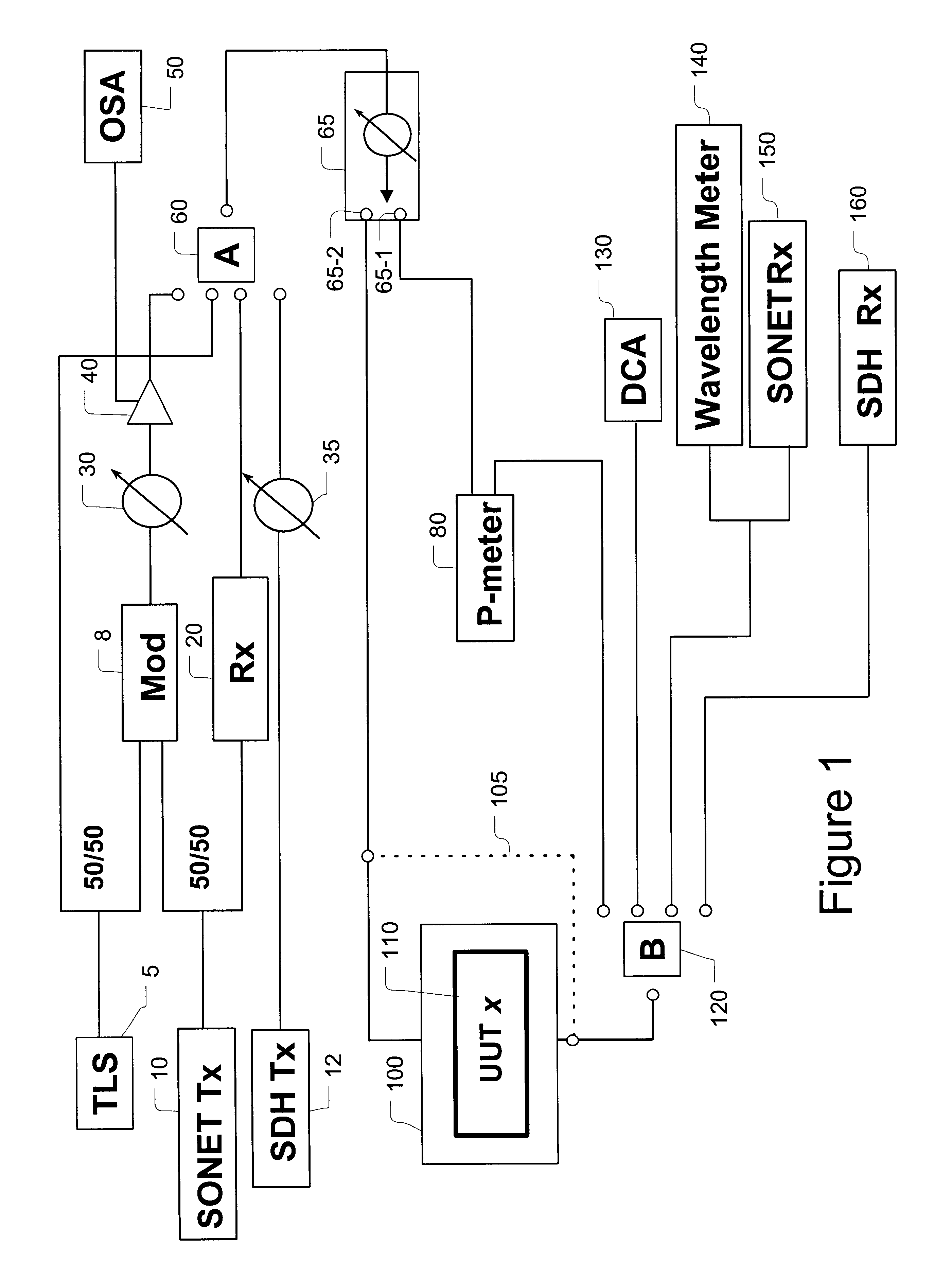
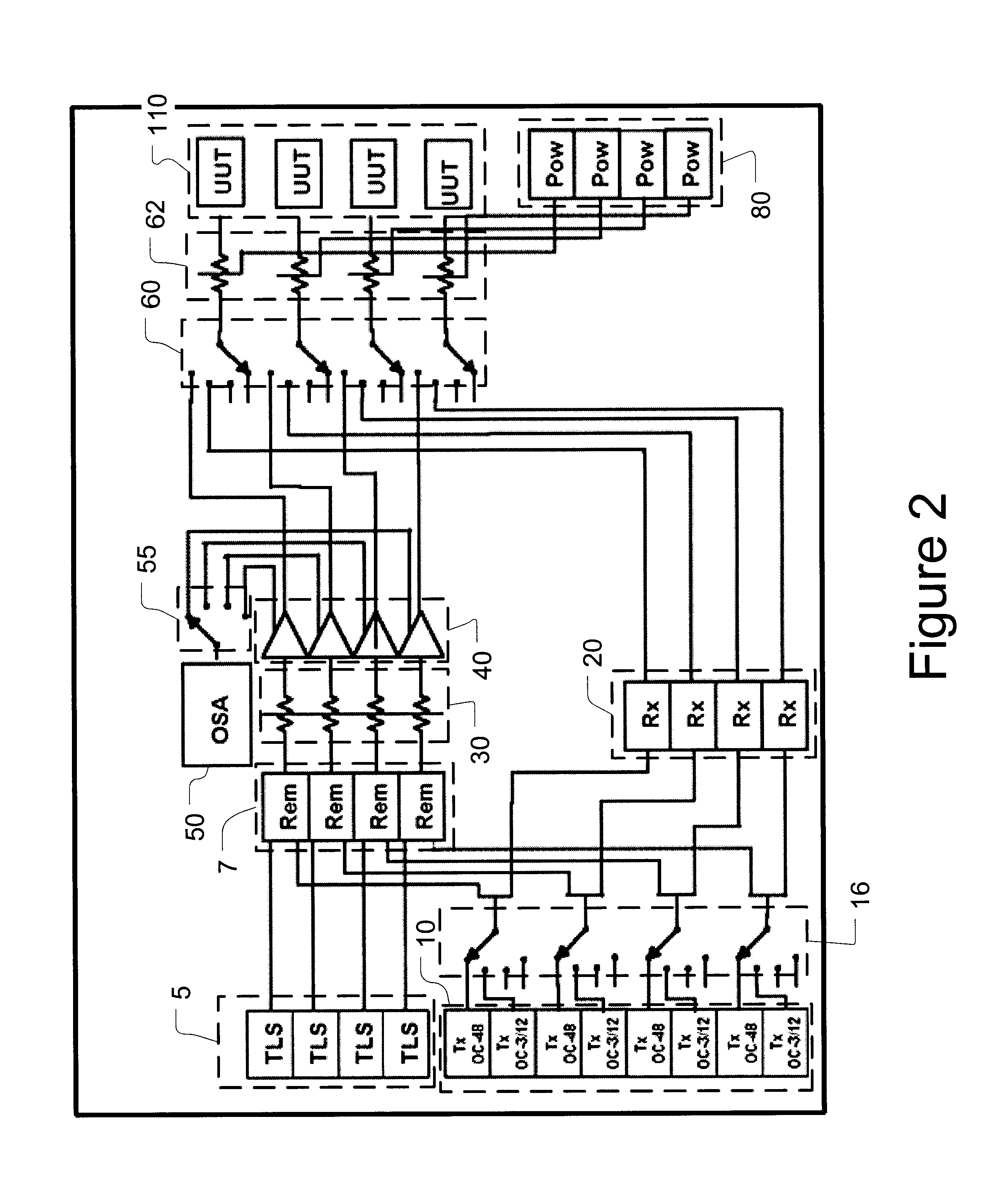
The following detailed description of the invention refers to the accompanying drawings. The same reference numbers in different drawings identify the same or similar elements. Also, the following detailed description does not limit the invention. Instead, the scope of the invention is defined by the appended claims and equivalents thereof.

The expression "optically communicates" as used herein refers to any connection, coupling, link or the like by which optical signals carried by one optical system element are imparted to the "communicating" element. Such "optically communicating" devices are not necessarily directly connected to one another and may be separated by intermediate optical components or devices.

Furthermore, the term "connection" and "operative connection" as used herein is a relative term and does not require a direct physical connection. For example, controller 70 may communicate with other elements by using a communication pathway over a fiber span, an Internet conne...


PUM

PropertyMeasurementUnit
wavelengthsaaaaaaaaaa
optical testaaaaaaaaaa

Abstract

A system for conducting optical tests on a plurality of optical modules includes a plurality of optical signal sources and optical signal degradation elements optically communicating with input switches. The input switches sources supply optical test signals to optical modules (units under test) plugged into a common shelf. Output optical switches supply the output signals to a range of optical test equipment. A controller utilizes a database of test recipes to supervise and control the optical signal sources, optical signal degradation elements, units under test, input switches, output switches, and test equipment to conduct a variety of optical tests on the modules. With this architecture it is possible to subject a variety of different optical modules to a variety of different optical tests.

Description

1. Field of InventionThe invention generally relates to testing and calibration of optical and electro-optical modules, generically referred to herein as "modules" or "optical modules." More specifically, the invention relates to systems, apparatuses and methods for performing parallel, asynchronous testing and calibration of optical and / or electro-optical modules.2. Description of Related ArtElectronic manufacturers that produce large volumes of identical components have sought to improve widely-used serial testing techniques by employing parallel testing schemes. Such parallel test schemes subject a large number of identical electronic devices to the same test. The test cycle for such electronic components is relatively short and the testing of a plurality of such components is initiated simultaneously. In other words, there is known a synchronous, parallel testing scheme for testing electronic components.Optical networking equipment manufacturing presents difficult challenges not...

Claims


Application Information

Patent Timeline
Patent Type & Authority Patents(United States)
IPC IPC(8): G01M11/00
CPCG01M11/33
Inventor COIN, BRYANRANSFORD, MICHAEL J.SCHWARTEN, DAVID A.JIANG, CHAODAR, IQBAL M.CSIPKES, ANDREI
Owner CIENA
Why Eureka
Try Eureka