
Optical Transceiver Integrated with Optical Time Domain Reflectometer Monitoring

a technology of optical time domain reflectometer and optical transceiver, which is applied in the direction of transmission monitoring, electromagnetic transceivers, electromagnetic transmission, etc., can solve the problems of difficult placement and wiring in server rooms, high cost of otdr equipment b>110/b>, etc., and achieve the effect of avoiding data monitoring and successful data monitoring

Active Publication Date: 2012-09-27
SOURCE PHOTONICS
View PDF3 Cites 40 Cited by
  • Summary
  • Abstract
  • Description
  • Claims
  • Application Information

AI Technical Summary

Benefits of technology

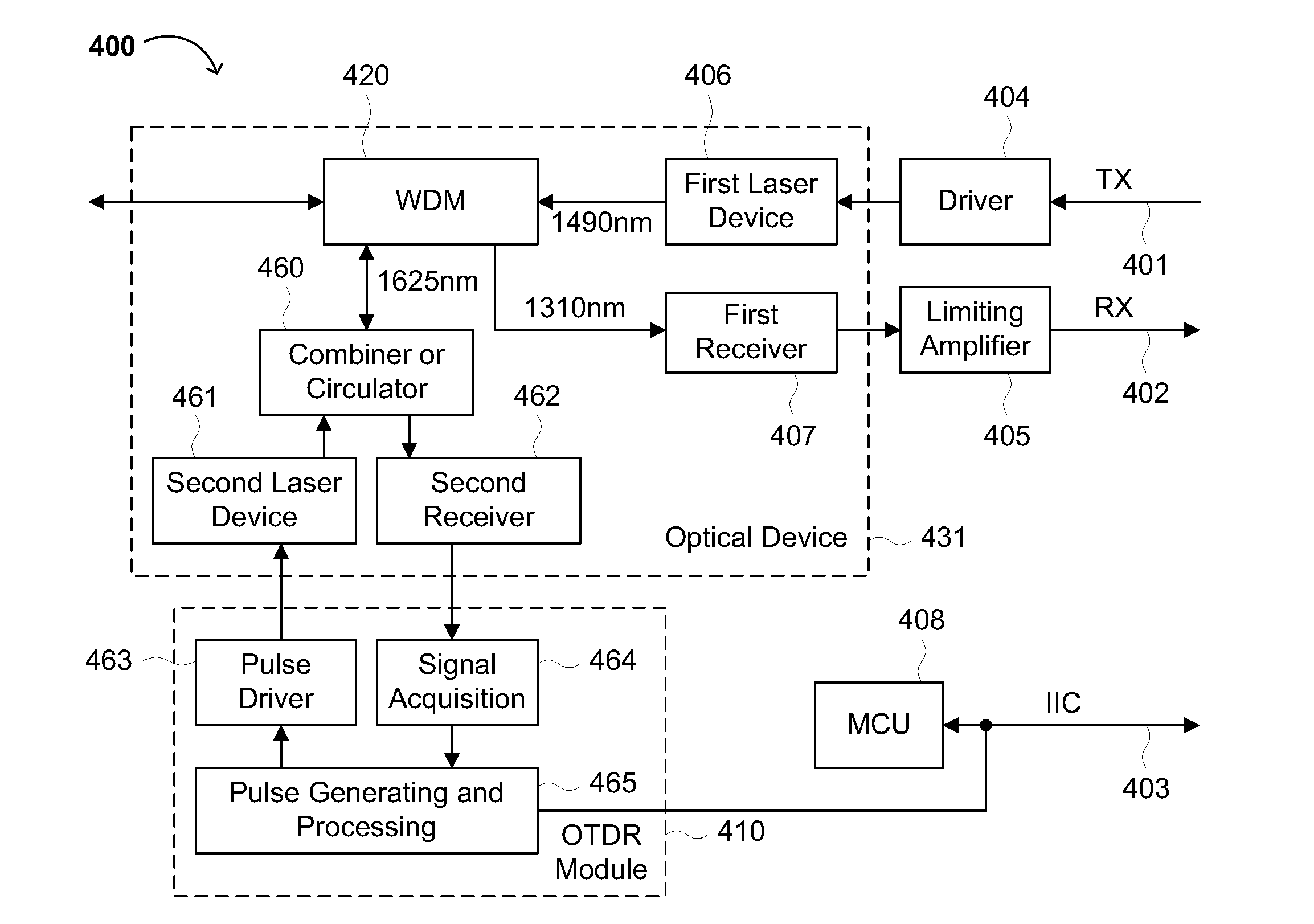
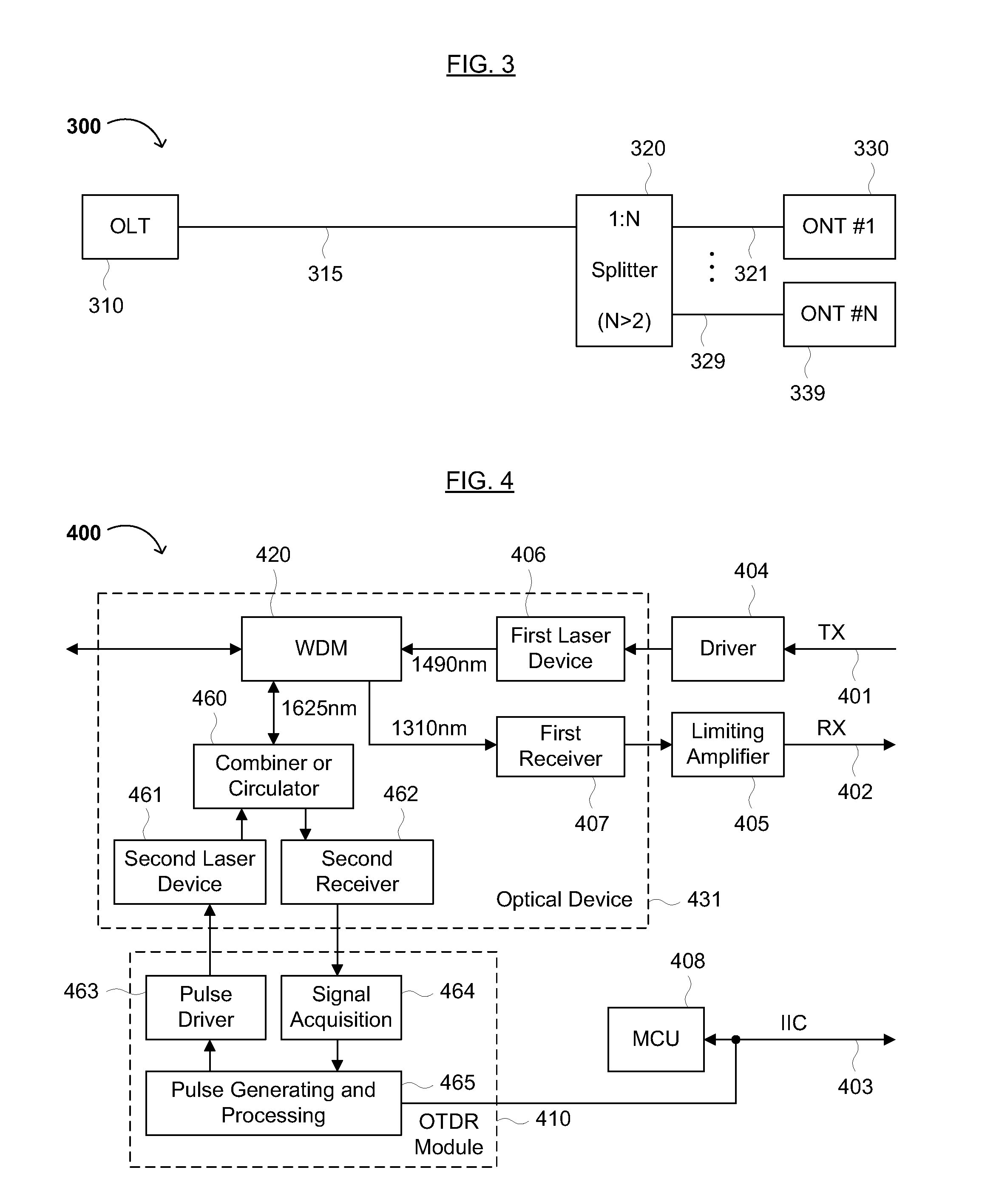
[0010]The present invention relates to an optical transceiver comprising an optical device comprising a wavelength division multiplexor or multiplexing system (WDM), a data signal driver, a data signal limiting amplifier, and an optical time domain reflectometer (OTDR) data processing module. Furthermore, the present optical transceiver integrates the OTDR data processing module to advantageously protect the optical transceiver and guarantee successful monitoring of data. The present invention advantageously minimizes and / or avoids (i) high costs associated with conventional OTDR equipment and (ii) difficulties in wiring such equipment (e.g., in an optical line terminal [OLT] and / or a passive optical network PON]).
[0016]Thus, the present optical transceiver, having an integrated OTDR monitoring system, advantageously protects conventional optical transceivers and guarantees successful monitoring of data (e.g., via an IIC interface). Furthermore, embodiments of the present invention can advantageously simplify network wiring and decrease system and network costs by decreasing the number of OTDR devices and WDM units.

Problems solved by technology

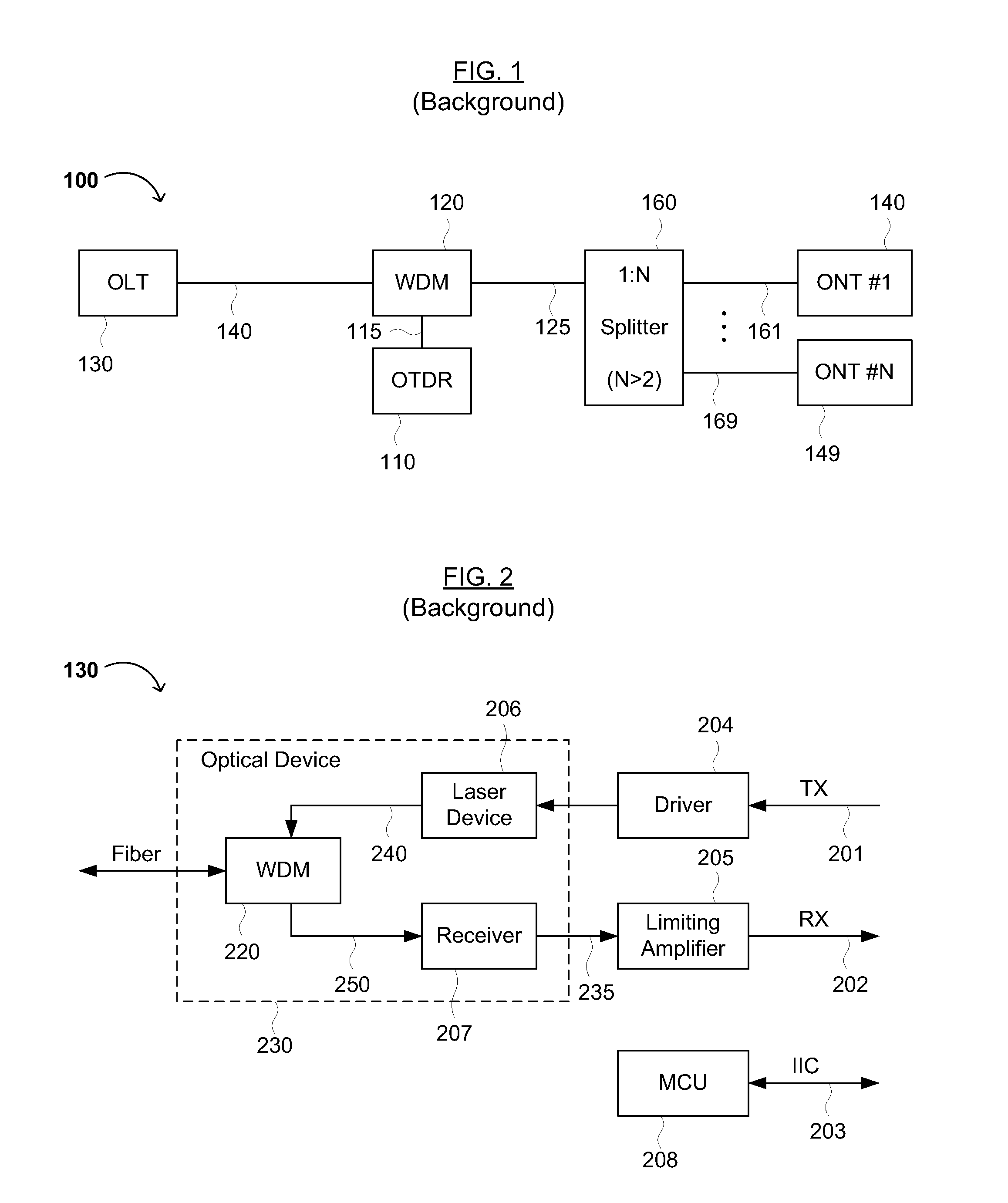
Generally, the OTDR equipment 110 is relatively expensive and difficult for placement and wiring in a server room, especially when adding additional WDMs 120 and OTDR equipment 110 to the conventional passive optical network 100.

Method used


Image

  • Optical Transceiver Integrated with Optical Time Domain Reflectometer Monitoring
  • Optical Transceiver Integrated with Optical Time Domain Reflectometer Monitoring
  • Optical Transceiver Integrated with Optical Time Domain Reflectometer Monitoring

Examples


Embodiment Construction

[0023]Reference will now be made in detail to various embodiments of the invention, examples of which are illustrated in the accompanying drawings. In order to achieve the objectives, technical solutions and advantages of the present invention more clearly, further details of the invention are described below with regard to the Figures. While the invention will be described in conjunction with the following embodiments, it will be understood that the descriptions are not intended to limit the invention to these embodiments. On the contrary, the invention is intended to cover alternatives, modifications and equivalents that may be included within the spirit and scope of the invention as defined by the appended claims. Furthermore, in the following detailed description, numerous specific details are set forth in order to provide a thorough understanding of the present invention. However, it will be readily apparent to one skilled in the art that the present invention may be practiced ...


PUM


Abstract

An optical transceiver having an integrated optical time domain reflectometer monitoring unit and methods for using the same are disclosed. The disclosure relates to an optical transceiver comprising an optical device comprising a wavelength division multiplexing system (WDM), a data signal driver, a data signal limiting amplifier, and an optical time domain reflectometer (OTDR) data processing module. Furthermore, the optical transceiver is particularly advantageous in an optical line terminal (OLT) and / or a passive optical network (PON). The integrated OTDR data processing module can protect the optical transceiver, ensure successful monitoring data, simplify network wiring and decrease system and network costs by decreasing the number of OTDR modules and WDM units.

Description

CROSS REFERENCE TO RELATED APPLICATION[0001]This application claims the benefit of Chinese Patent Application No. 201110071513.8, which was filed on Mar. 24, 2011, and is hereby incorporated by reference as if fully set forth herein.FIELD OF THE INVENTION[0002]The present invention generally relates to the field of passive optical networks and optical time domain reflectometer (OTDR) fiber testing. More specifically, embodiments of the present invention pertain to an optical transceiver with integrated OTDR monitoring, useful as an optical line terminal (OLT), and methods of manufacturing such optical transceivers.DISCUSSION OF THE BACKGROUND[0003]With increasing demand for data, voice / audio, video and other services, such as high-definition Internet protocol television (IPTV) and multi-media release systems, demanding higher bandwidth for passive optical network access technology is widely applied. A passive optical network (PON) refers to an optical distribution network (ODN) with...

Claims


Application Information

Patent Timeline
Patent Type & Authority Applications(United States)
IPC IPC(8): H04B10/08
CPCH04B10/071H04B10/40H04B10/272
Inventor ZHAO, FUQIANGYANG, YILU, YONG
Owner SOURCE PHOTONICS
Learn More