

Finite Impulse Response Filter For Producing Outputs Having Different Phases
- Summary
- Abstract
- Description
- Claims
- Application Information
AI Technical Summary
Problems solved by technology
Method used
Image

Examples
Embodiment Construction
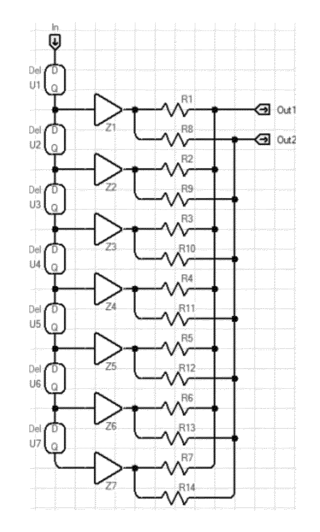
[0034]The present application describes the design and implementation of a finite impulse response (FIR) filter to create a plurality of output signals, each output signal having the same frequency but at a different phase shift from the other output(s). The phase shift is constant and independent of the frequency of the output signal.
[0035]It has been found that a FIR filter with multiple outputs of the same frequency and differing phases may be created by selecting different impedance values for each output as explained herein. The ability to maintain a constant phase difference regardless of frequency can be of significant use in situations in which the known technique of maintaining a fixed delay time described above fails to accomplish a desired result. While it is expected that one use of the described apparatus and method will be to generate a number of outputs of equally spaced phase shifts, such equal spacing is not necessary, and any desired set of phase shifts may be gene...
PUM
 Abstract
Description
Claims
Application Information