Hydraulic pressure control device

Inactive Publication Date: 2012-10-04
AISIN AW CO LTD
View PDF1 Cites 5 Cited by
  • Summary
  • Abstract
  • Description
  • Claims
  • Application Information

AI Technical Summary

Benefits of technology

[0010]In addition, the hydraulic pressure control device according to the aspect of the present invention controls the hydraulic pressure to the torque converter which engages the lock-up clutch using an engagement pressure corresponding to a difference in oil pressure between an engagement oil chamber and a disengagement oil chamber. The hydraulic pressure control device may further include a second switching valve that is selectively switchable between a first state in which the hydraulic pressure in the second oil passage is input to both the engagement oil chamber and the disengagement oil chamber and a second state in which the hydraulic pressure in the second oil passage is input to the disengagement oil chamber to be output from the engagement oil chamber, and the first switching valve and the second switching valve may be configured to be switchable using a common spool such that the first state of the first switching valv

Problems solved by technology

Therefore, a reduction in modulator pressure may make control of such valves unstable.
When the rotational speed of the e

Method used


Image

  • Hydraulic pressure control device
  • Hydraulic pressure control device
  • Hydraulic pressure control device

Examples


Embodiment Construction

[0016]Now, an embodiment of the present invention will be described below.

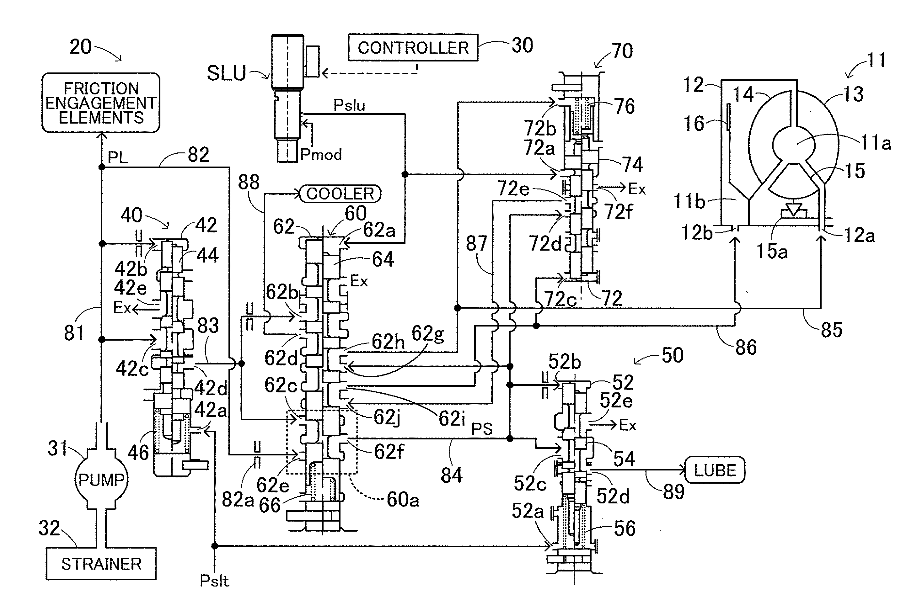
[0017]FIG. 1 is a diagram showing a schematic configuration of a hydraulic pressure control device 20 according to an embodiment of the present invention. The hydraulic pressure control device 20 according to the embodiment is formed as a device that is provided in an automobile incorporating an engine and an automatic transmission (all not shown) and that controls a hydraulic pressure to be supplied to a torque converter 11 that receives engine torque output to a crankshaft of the engine to transfer the input torque to an input shaft of the automatic transmission.

[0018]The torque converter 11 includes a pump impeller 13 connected to the crankshaft via a converter cover 12, a turbine runner 14 connected to the input shaft and disposed opposite the pump impeller 13, a stator 15 which is disposed between the pump impeller 13 and the turbine runner 14 and to which a one-way clutch 15a that allows rotation only in...


PUM


Abstract

A hydraulic pressure controller, which controls hydraulic pressure supplied to a torque converter including a lock-up clutch that is engageable using a hydraulic pressure from a mechanical pump, including a first pressure regulation valve that regulates pressure in a first passage connected to the pump while discharging oil in the first passage to a discharge passage; a bypass passage branched from the first passage bypassing the first pressure regulation valve; a first switching valve selectively switchable between a first state in which the bypass passage and a second passage are connected to each other and a second state in which the discharge passage and the second passage are connected to each other; and a second pressure regulation valve that regulates a hydraulic pressure in the second passage. The first switching valve is switchable into the first state to engage the clutch and into the second state to disengage the clutch.

Description

INCORPORATION BY REFERENCE[0001]The disclosure of Japanese Patent Application No. 2011-074989 filed on Mar. 30, 2011 including the specification, drawings and abstract is incorporated herein by reference in its entirety.BACKGROUND OF THE INVENTION[0002]The present invention relates to a hydraulic pressure control device, and more particularly to a hydraulic pressure control device that controls supply of a hydraulic pressure to a torque converter including a lock-up clutch that is engageable using a hydraulic pressure from a mechanical pump driven by power from a motor.DESCRIPTION OF THE RELATED ART[0003]Hitherto, there has been proposed a hydraulic pressure control device including a primary regulator valve that regulates a hydraulic pressure from a hydraulic pump driven by power from an engine to a line pressure along with discharge of an excessive pressure, a secondary regulator valve that regulates the excessive pressure discharged from the primary regulator valve to a secondary...

Claims


Application Information

Patent Timeline
IPC IPC(8): F16D33/02
CPCF16H61/143
Inventor JINNO, TOMOYASHIMIZU, TETSUYAISHIKAWA, KAZUNORI
Owner AISIN AW CO LTD
Why Eureka
Try Eureka