Wireless Power Transmittal

a coupled inductor and power transmission technology, applied in the direction of transformer/inductance circuit, inductance, circuit arrangement, etc., can solve the problems of insufficient power transmission capability, inability to transmit power using inductive resonance, and inefficient systems, so as to improve data transmission functionality, improve the convenience of wireless charging system, and improve the effect of coupled inductor system power transfer

Active Publication Date: 2012-10-04
TRIUNE SYST LP
View PDF8 Cites 51 Cited by
  • Summary
  • Abstract
  • Description
  • Claims
  • Application Information

AI Technical Summary

Benefits of technology

[0013]The invention has advantages including but not limited to one or more of, improved coupled inductor system power transfer, improved data transmission functionality, improved convenience in wireless charging systems, and reduced costs. These and other potential advantageous, features, and benefits of the present invention can be understood by one skilled in the arts upon careful consideration of the detailed description of representative embodiments of the invention in connection with the accompanying drawings.

Problems solved by technology

Challenges inherent in such systems include providing efficiency in transferring power.
Inefficient systems generate excess heat and are limited in their maximum power transfer capability.
Techniques using inductive resonance can transmit power, but are limited in their utility, in part by the geometry of charging systems known in the art.

Method used


Image

  • Wireless Power Transmittal
  • Wireless Power Transmittal
  • Wireless Power Transmittal

Examples


Embodiment Construction

[0023]The present patent application is related to U.S. patent application Ser. No. 13 / 430,338 which shares at least one common inventor with the present application and has a common assignee. Said related application is hereby incorporated herein for all purposes by this reference.

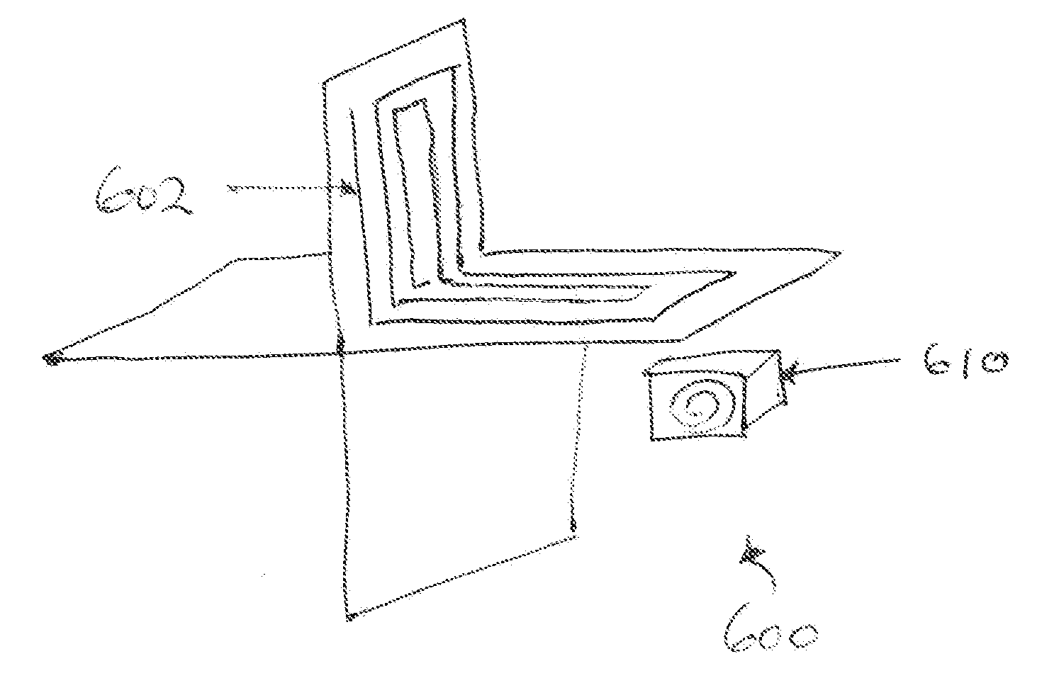
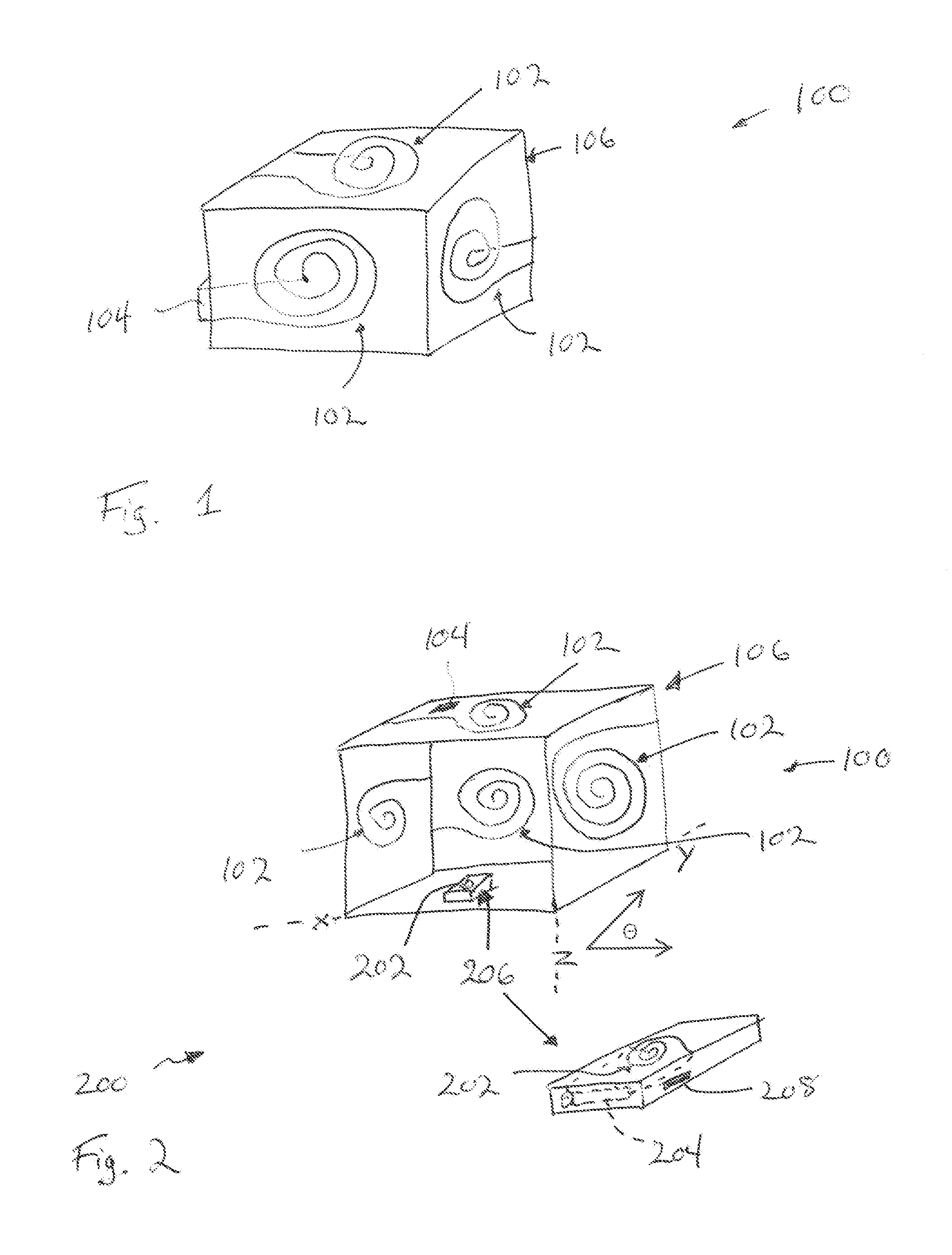
[0024]In the presence of an active primary coil, if a load is connected to the secondary coil of a coupled inductor system, an electric current flows in the secondary coil, and electrical energy is then transferred from the primary coil to the secondary coil, and ultimately to a load connected to the secondary side. An example of a preferred embodiment of apparatus for wireless power transmittal according to the invention is shown in FIG. 1. The apparatus 100 includes a number of primary coils 102 for transmitting power to a secondary side receiver (not shown in FIG. 1). A driver circuit 104 is coupled to the coils 102. Preferably, the driver circuit 104 is capable of adjustment in terms of frequency and ...


PUM


Abstract

Wireless power transmittal apparatus and systems are disclosed in which transmitter and receiver inductors, or coils, are coupled in configurations for wirelessly transferring power and / or data among them. In preferred implementations, a plurality of non-coplanar primary side coils are provided in power transmittal apparatus for transmitting power, or power and data.

Description

PRIORITY ENTITLEMENT[0001]This application is entitled to priority based on Provisional Patent Application Ser. No. 61 / 468,685 filed on Mar. 29, 2011, which is incorporated herein for all purposes by this reference. This application and the Provisional Patent Application have at least one common inventor.TECHNICAL FIELD[0002]The invention relates to coupled inductor systems. More particularly, the invention relates to coupled inductor systems for use in wireless power and data transfer applications. In preferred embodiments employed in wireless power applications, the invention relates to the more efficient utilization of energy resources.BACKGROUND OF THE INVENTION[0003]Inductive coupling is an effect used to transfer electrical energy from one circuit to an adjacent circuit through inductive coils. A variable current on a primary coil is used to create a varying magnetic field, and thus a voltage, in a secondary coil. Wireless charging systems employing inductive coupling are usef...

Claims


Application Information

Patent Timeline
Patent Type & Authority Applications(United States)
IPC IPC(8): H02J17/00
CPCH01F38/14H02J5/005H02J50/90H02J50/50H02J50/80H02J50/12
Inventor TEGGATZ, ROSS E.CHEN, WAYNE T.
Owner TRIUNE SYST LP
Why Eureka
Try Eureka