

Squirrel-cage rotor and production method thereof
a rotor and cage technology, applied in the direction of solid insulation, dynamo-electric machines, electrical apparatus, etc., can solve the problems of excessive increase of the grain size of the conductor, difficult control of the cooling rate, and degradation of the formed conductor, etc., and achieve the effect of sufficient strength
- Summary
- Abstract
- Description
- Claims
- Application Information
AI Technical Summary
Benefits of technology
Problems solved by technology
Method used
Image

Examples
first embodiment
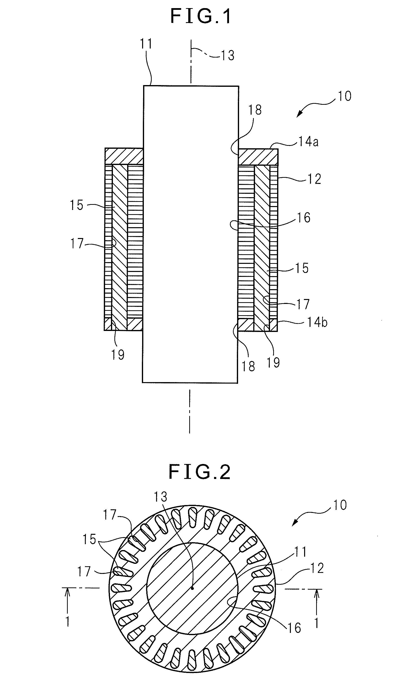
[0029]Hereinafter, an embodiment of the present invention will be explained with reference to the drawings. FIG. 1 is a sectional view of a squirrel-cage rotor 10 according to the invention, along a rotation axis of rotor 10, and FIG. 2 is a sectional view of rotor 10, perpendicular to the rotation axis of rotor 10. Squirrel-cage rotor 10 is attached to a rotation shaft 11 (for example, a column shaft). Rotor 10 has a cylindrical core 12, a pair of conductive annular end rings 14a, 14b positioned at both ends of core 12 in relation to the direction of a rotation shaft 11 (or a rotation axis 13 of core 12) so that the end rings sandwich core 12, and a plurality of conductive bars 15 extending through core 12 in the direction parallel to rotation axis 13.
[0030]Squirrel-cage rotor 10 used as a rotor of an induction motor is known. When rotor 10 is incorporated in the induction motor, a stator is positioned for generating a rotating magnetic field around rotor 10 about rotation axis 13....
second embodiment
[0040]FIG. 4 is a sectional view of a squirrel-cage rotor 10a according to the invention, along a rotation axis 13 of rotor 10a. The same reference numerals are added to components of rotor 10a, which are equivalent to the components of rotor 10. Rotor 10a is attached to rotation shaft 11, similarly to the above. In rotor 10a, conductive bars 15 are formed by the cold spraying process, as well as upper conductive end ring 14a. As a result, conductive end ring 14a and conductive bars 15 are integrally formed. Through holes 19 are formed in lower conductive end ring 14b, similarly to the above. In other words, as conductive end ring 14b, a processed product, which is machined in a predetermined shape, is used. The lower ends of conductive bars 15 are positioned within through holes 19.
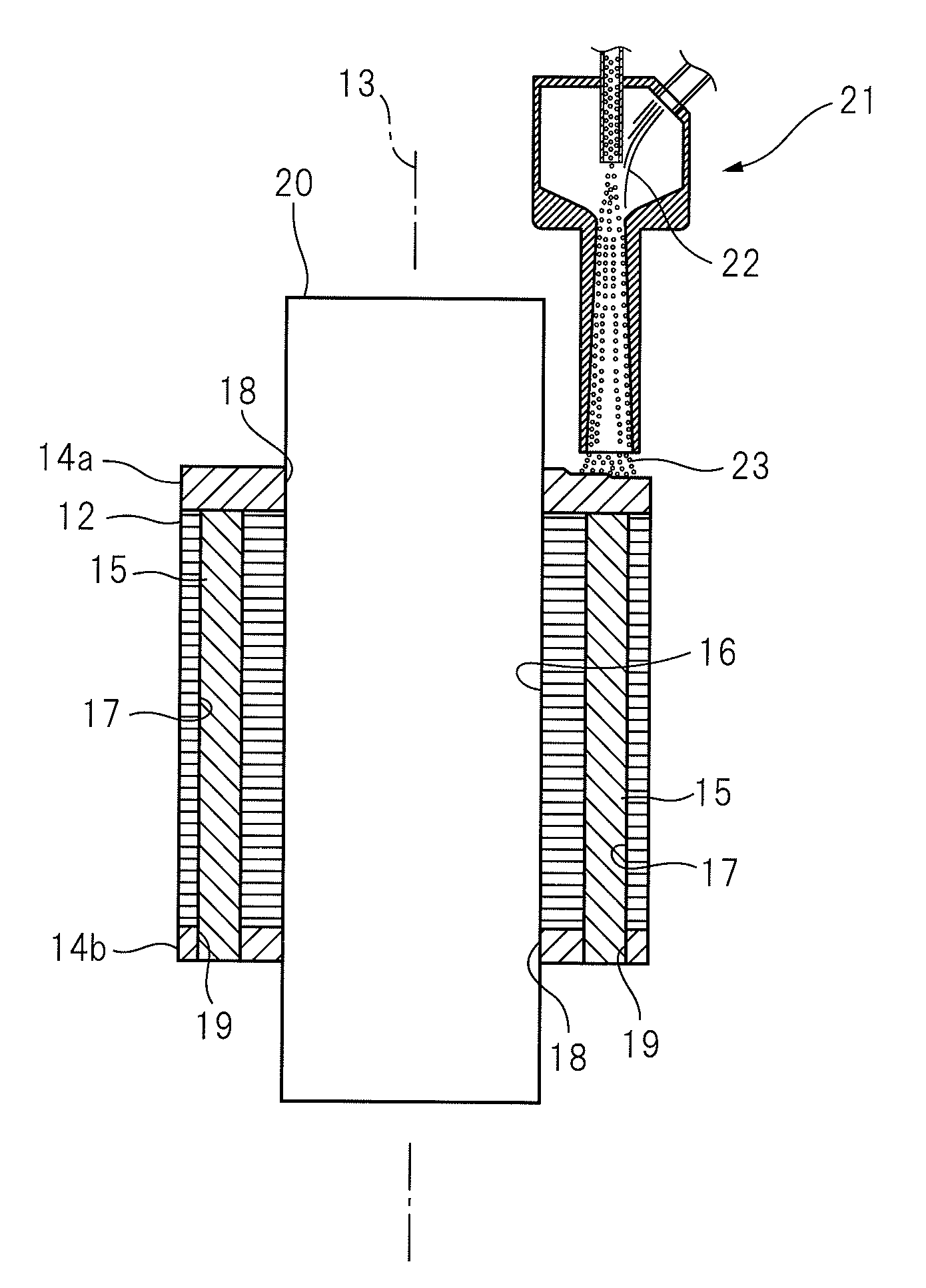
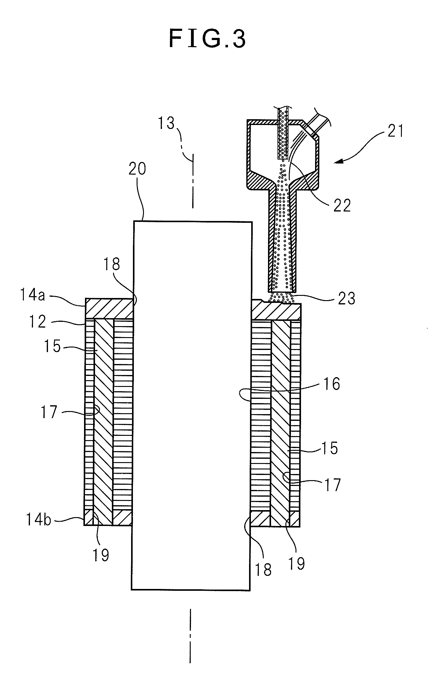
[0041]In producing squirrel-cage rotor 10a, conductive end ring 14b is attached to the assembly of core 12 mounted to fixture 20, similarly to the above. Then, as shown in FIG. 5, Laval nozzle 21 is inse...
third embodiment
[0043]FIG. 6 is a sectional view of a squirrel-cage rotor 10b according to the invention, along a rotation axis 13 of rotor 10b. The same reference numerals are added to components of rotor 10 or 10a, which are equivalent to the components of rotor 10 or 10a. Rotor 10b is attached to rotation shaft 11, similarly to the above. In rotor 10b, lower conductive end ring 14b is formed by the cold spraying process, as well as upper conductive end ring 14a and conductive bars 15. As a result, conductive end rings 14a, 14b and conductive bars 15 are integrally formed. In addition, since a processed product, which is machined in a predetermined shape, is not used, through holes 19 are not formed in lower end ring 14b.
[0044]In producing squirrel-cage rotor 10b, as shown in FIG. 7, Laval nozzle 21 is directed toward the outer periphery of rotor 10b. Rotor 10b is rotated about rotation axis 13, and conductor particles 23 are sprayed toward core 12 and rotation axis 13. As a result, the coating ...
PUM
| Property | Measurement | Unit |
|---|---|---|
| Electrical conductor | aaaaa | aaaaa |
| Strength | aaaaa | aaaaa |
Abstract
Description
Claims
Application Information