Electric motor

a technology of electric motors and motors, applied in the direction of dynamo-electric machines, electrical apparatus, magnetic circuit shapes/forms/construction, etc., can solve the problems of low winding efficiency, limited winding number, and inability to ensure the concentricity of the pole arc of the stator pole, so as to achieve the effect of lowering the motor cos

Inactive Publication Date: 2012-10-04
JOHNSON ELECTRIC SA
View PDF3 Cites 7 Cited by
  • Summary
  • Abstract
  • Description
  • Claims
  • Application Information

AI Technical Summary

Benefits of technology

[0025]According to the embodiments of the present invention, the concentricity of the pole arcs of the stator poles can be assured, the end brackets can be mounted on a planar surface and the motor cost can be lowered.

Problems solved by technology

It is not convenient to wind windings on a closing structure, so the winding efficiency is low and sometimes the number of turns of the winding is limited.
However, the concentricity of the pole arcs of the stator poles can not be assured as undesired position deviation between the pole arcs may generate during the assembly of the divided bodies.

Method used


Image

  • Electric motor
  • Electric motor
  • Electric motor

Examples


second embodiment

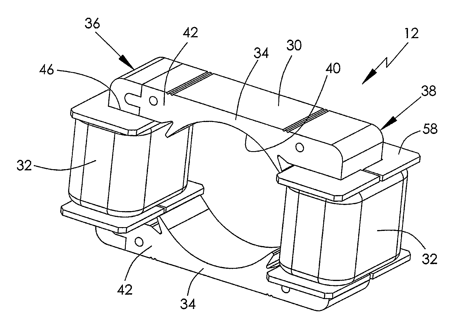
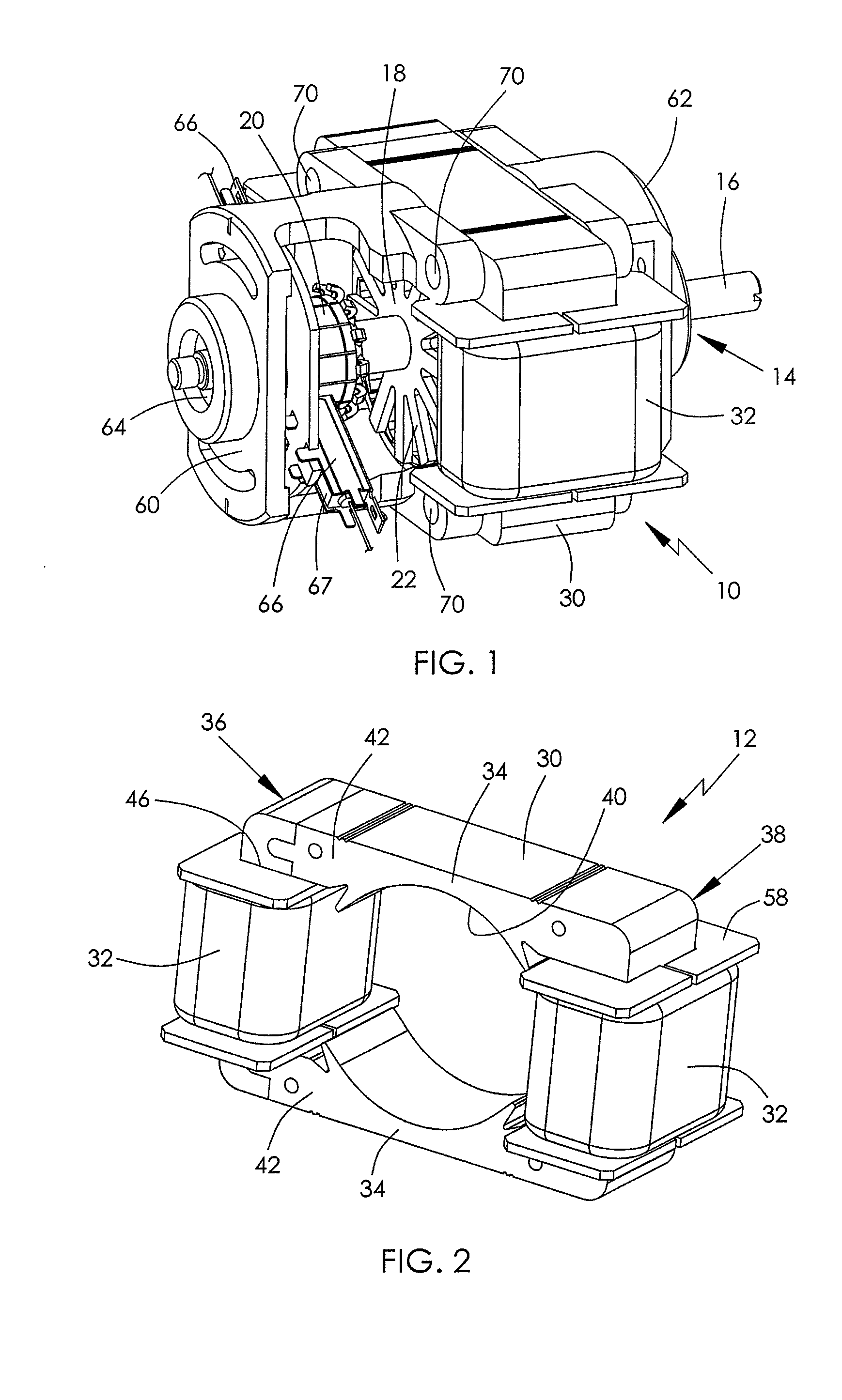
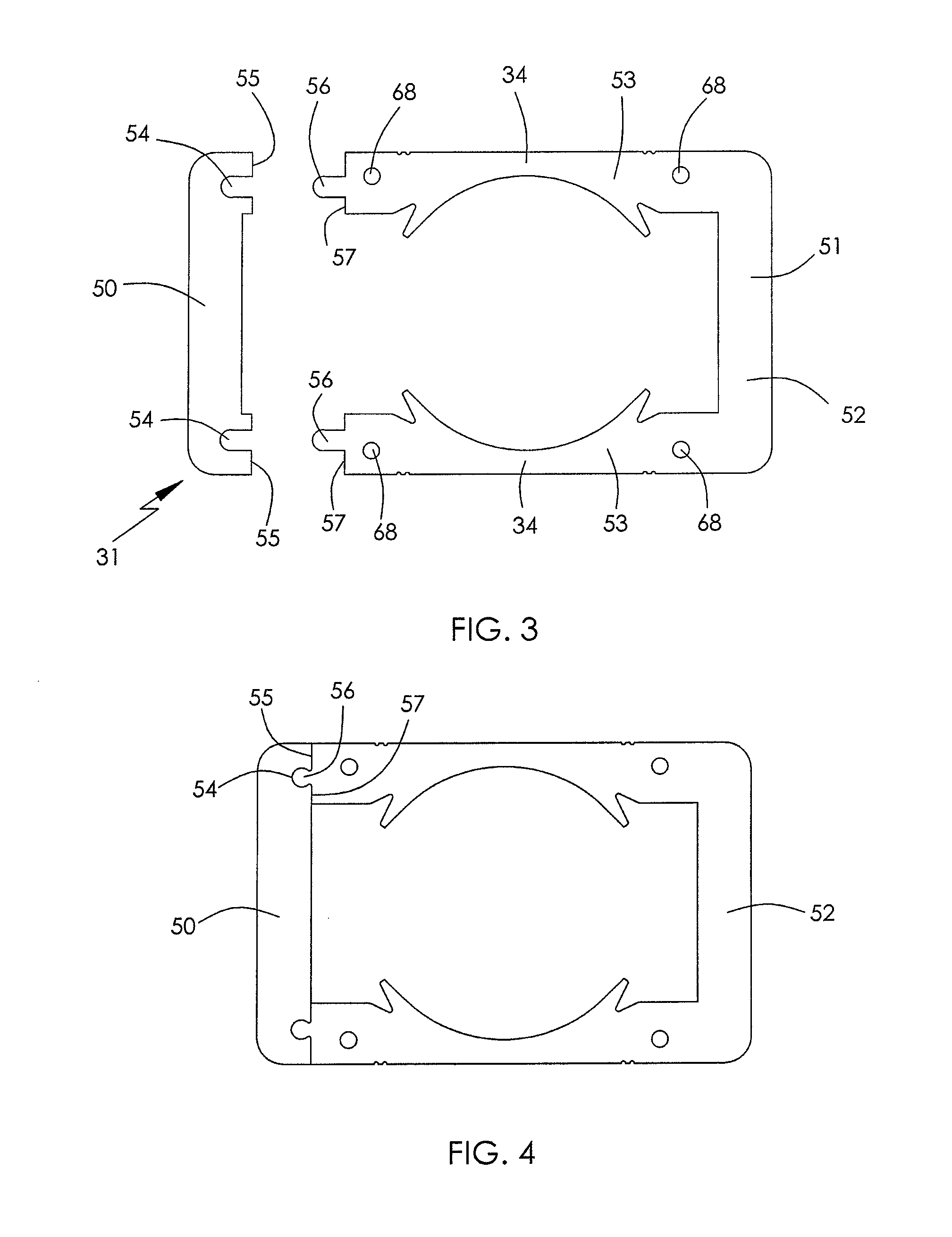
[0042]FIG. 7 is a view of an electric motor 80 in accordance with the present invention. FIG. 8 is a plan view of the motor 80 with end brackets removed. In this embodiment, the stator lamination has a strip member 50 and a U-shaped member 52 which are joined together by two pairs of joining surfaces 55 and 57 having grooves 54 and projecting ribs 56. One of the two stator poles 34 inwardly extends from the base 51 of the U-shaped member 52 and the other one inwardly extends from the strip member 50. Four stator windings 32 are respectively wound about portions of the U-shaped yokes 36 and 38 connecting the stator poles and generate two magnetic poles with opposite polarity at the stator poles 34. Each end bracket 60, 62 bridges between the two branches 53 of the U-shaped member 52. The end brackets 60, 62 and the stator core 30 are fixed together by screws inserted through mounting holes 68, 70 on the end bracket and the branches 53. In this embodiment, the magnetic potential diffe...

third embodiment

[0043]FIG. 9 partially shows an electric motor 82 in accordance with the present invention. FIG. 10 is a view of a stator lamination of the motor 82. In this embodiment, the stator lamination 31 has two U-shaped members 84 which are joined together by two pairs of joining surfaces 55 and 57 having grooves 54 and projecting ribs 56. The two pairs of joining surfaces are respectively disposed at the stator poles 34. Each stator pole 34 is constituted by two stator pole portions 88 respectively extending from two opposite branches 86 of the two U-shaped members 84. Four stator windings 32 are respectively wound about the U-shaped yokes 36 and 38 at four corners. By this configuration, stator windings 32 with more turns can be allowed. Each end bracket 60, 62 bridges between two bases 87 of the two U-shaped members 84 and are preferably made of magnetically conductive material to lower the cost, as the magnetic potential difference between the connection points is low.

fourth embodiment

[0044]FIG. 11 partially shows a stator core and a rotor core of an electric motor 90 in accordance with the present invention. In this embodiment, the stator lamination 31 is constituted by four separate strip members 92˜95 which are joined together by four pairs of joining surfaces 55 and 57 at four corners. The groove 54 and the projecting rib 56 of each pair of joining surfaces form a joining structure. The two stator poles 34 inwardly extend from two opposite strip members 93 and 95. One or two stator coils (not shown) may be disposed on each U-shaped yoke 36, 38.


PUM


Abstract

An electric motor includes a stator and a rotor installed in the stator. The stator has a laminated stator core and at least two stator windings wound on the stator core. The stator core has at least two stator poles facing the rotor and at least two yokes connecting adjacent stator poles. T stator core is constituted by at least two separate members joined together. The at least two stator poles are only arranged at a single one of the at least two separate members.

Description

CROSS REFERENCE TO RELATED APPLICATIONS[0001]This non-provisional patent application claims priority under 35 U.S.C. §119(a) from Patent Application No. 201110085588.1 filed in The People's Republic of China on Apr. 1, 2011.FIELD OF THE INVENTION[0002]This invention relates to an electric motor and in particular, to a stator structure of an electric motor.BACKGROUND OF THE INVENTION[0003]A single phase series motor is also known as a universal motor as it can operate on either AC or DC power. It is a single phase motor with a commutator whose rotor windings are connected in series with stator windings via brushes. Due to its characteristics of high rotating speed, small size, high starting torque, convenient speed regulation and series excitation, the universal motor is commonly used for driving low power appliances that need a high rotating speed, small size and low weight, such as medical devices, power tools, and domestic electric appliances and so on.[0004]A typical known univer...

Claims


Application Information

Patent Timeline
Patent Type & Authority Applications(United States)
IPC IPC(8): H02K1/18
CPCH02K1/146H02K1/18
Inventor LI, YUEJIANG, MAO XIONGLIU, BAO TINGZHOU, CHUI YOUGAN, JIN YUNZHAO, JIANLI, YONGZHANG, HONG WEI
Owner JOHNSON ELECTRIC SA
Why Eureka
Try Eureka