
Motor

a technology of motors and bearings, applied in the direction of dynamo-electric machines, electrical equipment, supports/enclosements/casings, etc., can solve the problem that the structure cannot securely support the bearing against the axial load

Active Publication Date: 2015-10-08
LG INNOTEK CO LTD
View PDF2 Cites 1 Cited by
  • Summary
  • Abstract
  • Description
  • Claims
  • Application Information

AI Technical Summary

Benefits of technology

The present invention allows for the motor housing to be made by deep drawing, reducing manufacturing costs. Additionally, it ensures stable bearing support even when there is an axial load.

Problems solved by technology

However, such a structure may not securely support the bearing against the axial load.

Method used


Image

  • Motor
  • Motor
  • Motor

Examples


Embodiment Construction

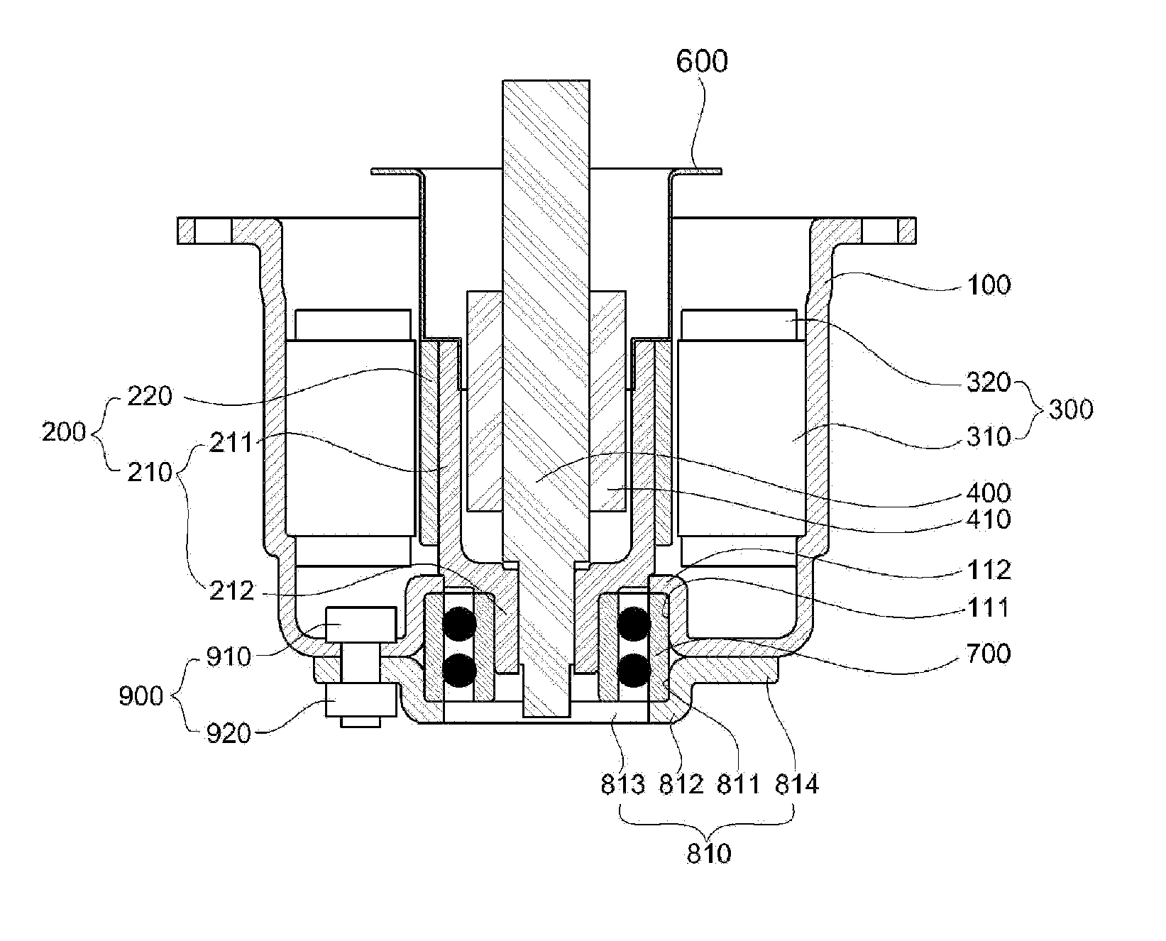
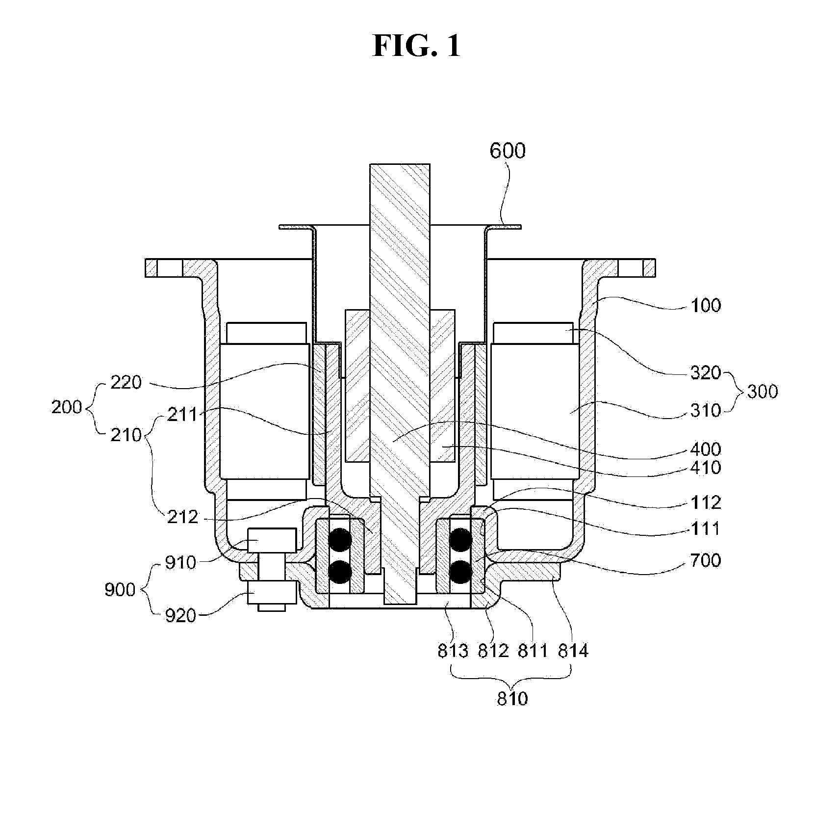
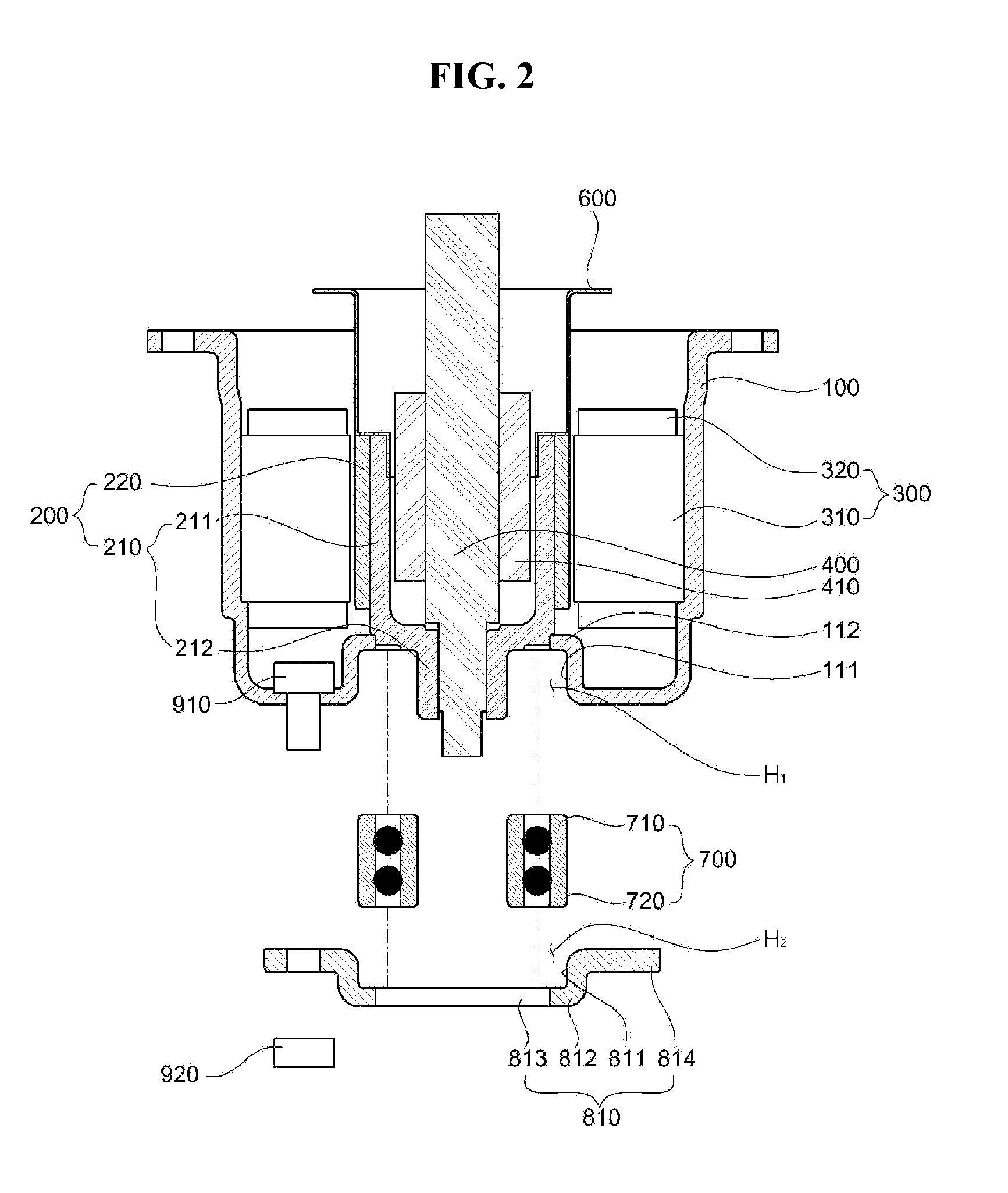
of Main Elements:100: housing 111, 121: first receiving part112, 122: first protruding part 200: rotor300: stator400: rotating shaft410: motion member 700: bearing810, 820, 830, 840, 850, 860, 870, 880: holder

DETAILED DESCRIPTION OF EXEMPLARY EMBODIMENTS

[0038]Although the present invention can be modified variously and have several embodiments, specific exemplary embodiments are illustrated in the accompanying drawings and will be described in detail in the detailed description. However, the present invention is not limited to the embodiments, and it should be understood that the present invention comprises all of equivalents and substitutes included in the technical scope and spirit of the invention.

[0039]Terms including ordinal numbers such as “first,”“second,” etc. can be used to describe various components, but the components are not limited by those terms. The terms are used merely for the purpose of distinguishing one component from another. For example, a first component may ...


PUM


Abstract

Disclosed is a motor including a housing having a first receiving part formed at one side thereof, a stator disposed in the housing, a rotor disposed in the housing, a rotating shaft rotated along with the rotor, a holder coupled to one side of the housing, and a bearing disposed between the first receiving part and the holder to support a rotation of the rotor.

Description

CROSS-REFERENCE TO RELATED APPLICATIONS[0001]This application claims the benefit under 35 U.S.C. §119 of Korean Patent Application Nos. 10-2014-0040565, filed Apr. 4, 2014, and 10-2014-0193902, filed Dec. 30, 2014, which are herein incorporated by reference in their entirety.BACKGROUND[0002]1. Field of the Invention[0003]The present invention relates to a motor having enhanced reliability with respect to an axial load.[0004]2. Discussion of Related Art[0005]Generally, in a motor, a stator is disposed at an inner circumferential surface of a housing, and a rotor is disposed at a center of the stator. The rotor is rotated by an electromagnetic interaction with the stator so as to transmit power to an outside.[0006]For example, a motion member coupled to a rotating shaft of the motor may press an external master cylinder, and thus may operate a brake system. However, the motor receives a large axial load, while pressing the master cylinder, and the axial load is transmitted to a bearin...

Claims


Application Information

Patent Timeline
IPC IPC(8): H02K5/173H02K7/10
CPCH02K7/10H02K5/1735H02K5/15H02K7/06
Inventor KIM, JIN HOKIM, SEONG JINPARK, KYUNG SANGPARK, CHANG HYUNSHIM, WOO SEOB
Owner LG INNOTEK CO LTD
Learn More