Stacked Via Structure For Metal Fuse Applications

a technology of metal fuse and via structure, applied in the field of electromechanical fuses, can solve the problem that the fuse structure promotes failure in certain areas of the fus

Active Publication Date: 2012-10-04
SONY CORP
View PDF2 Cites 13 Cited by
  • Summary
  • Abstract
  • Description
  • Claims
  • Application Information

AI Technical Summary

Benefits of technology

[0016]According to another embodiment of the present invention, a method for electrically detecting damage in dielectric regions of a fuse is provided. The method includes the steps of: applying voltage between a negative current connection and an positive current connection; measuring current between a positive current connection and a negative current connection; and detecting damage in a dielectric region wherein damage exists and has extended where a short circuit is measured between the positive current connection and the negative current connection.
[0017]According to a further embodiment of the present invention, a fuse structure for detecting material from damage by a blown fuse is provided. The fuse structure includes: a first dielectric layer disposed on the dielectric material having a first conductive via and a first conductive line disposed in a first cavity formed in the first dielectric layer, the first conductive via and the first conductive line having a first liner disposed along at least vertical surfaces of the first cavity; a second conduc

Problems solved by technology

The fuse structure promotes fail

Method used


Image

  • Stacked Via Structure For Metal Fuse Applications
  • Stacked Via Structure For Metal Fuse Applications
  • Stacked Via Structure For Metal Fuse Applications

Examples


Embodiment Construction

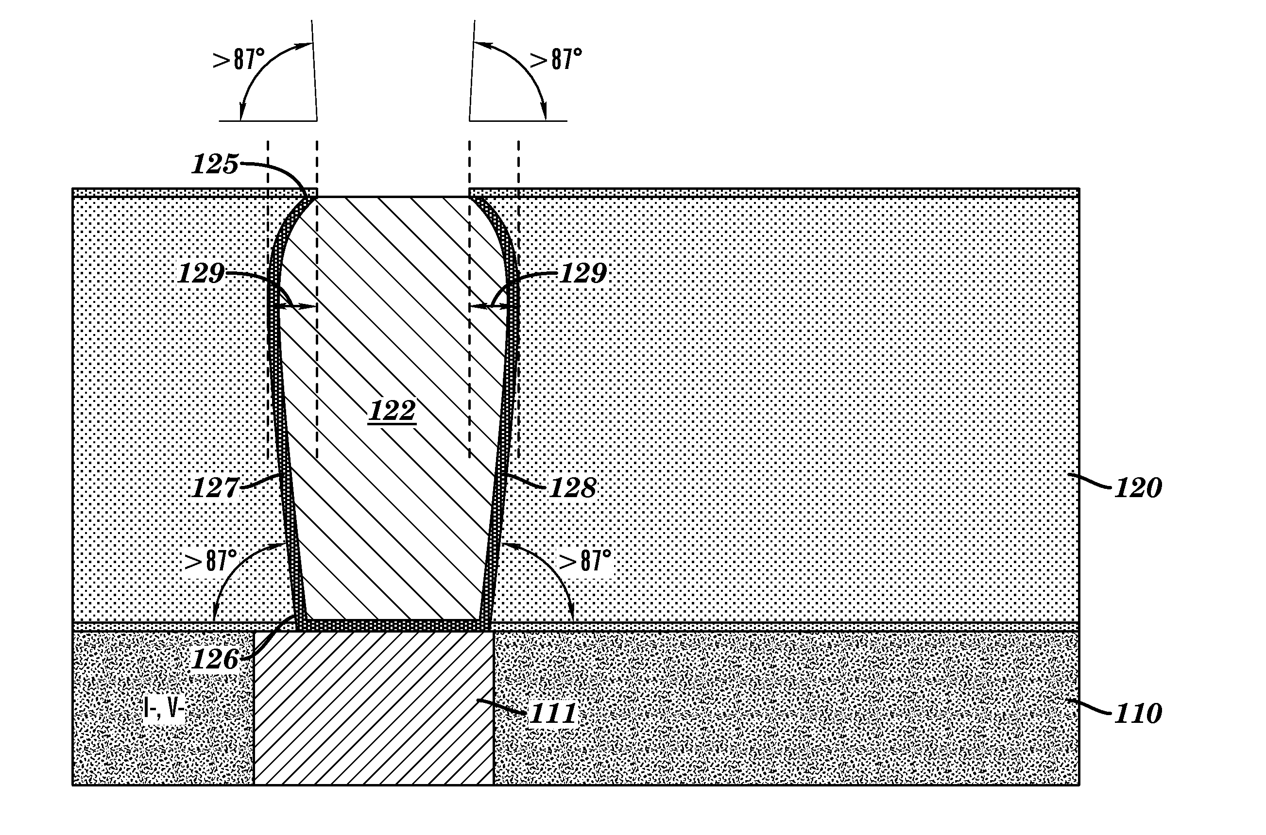
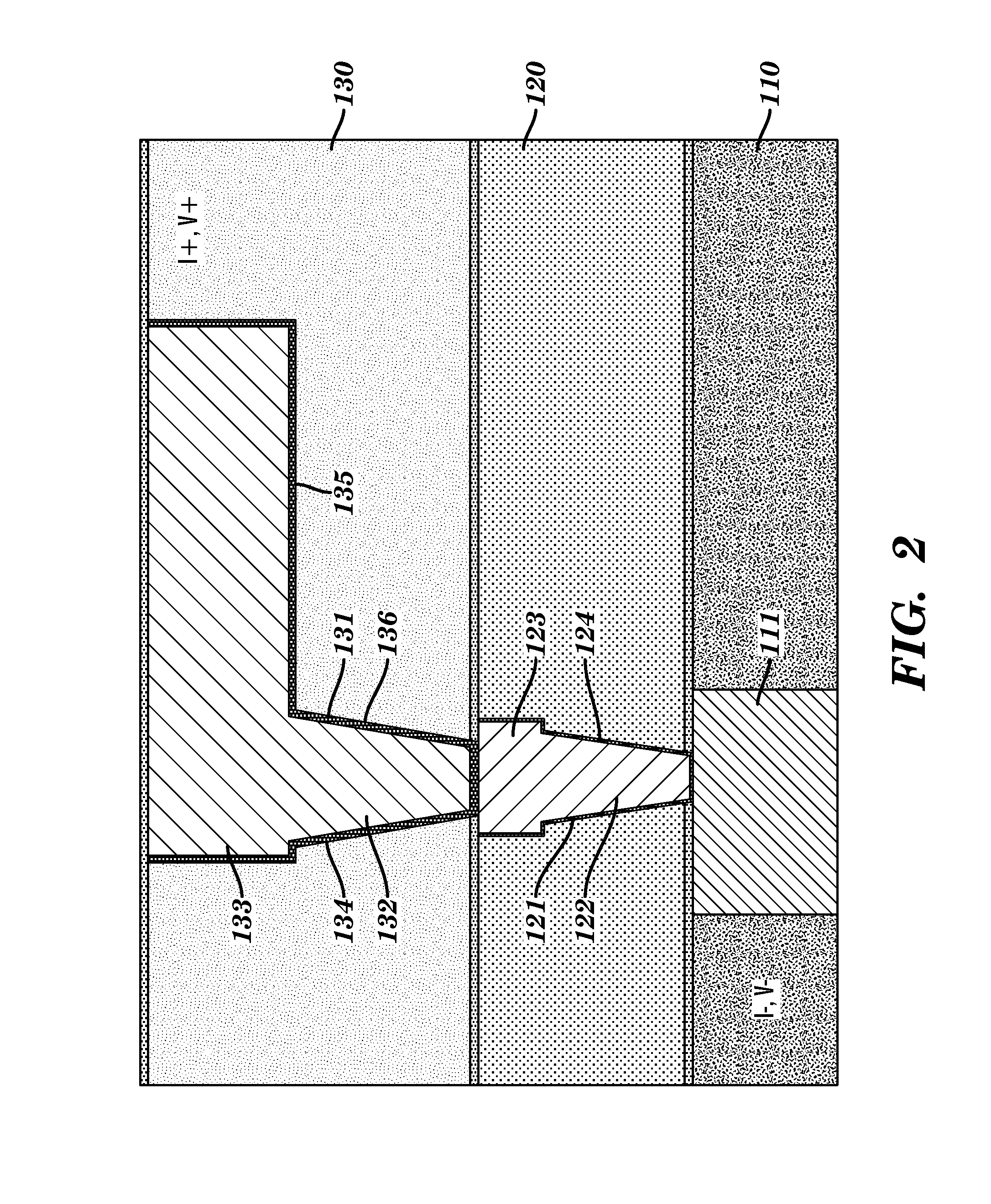
[0027]The present invention provides a back end of the line (BEOL) fuse structure having a stack of vias. The stacking of vias leads to high aspect ratios, which makes liner and seed coverage inside of the vias poorer. This weakness in the liner and seed layers leads to a higher probability of electromigration (EM) failure. The present invention includes a fuse structure to address failures due to poor liner and seed coverage. Design features allow for determining the extent of the damaged region following fuse programming. Other design features make it possible to prevent further propagation of the damaged dielectric region.

[0028]The following describes embodiments of the present invention with reference to the drawings. The embodiments are illustrations of the invention, which can be embodied in various forms. The present invention is not limited to the embodiments described below, rather representative for teaching one skilled in the art how to make and use it. Some aspects of th...


PUM


Abstract

A back end of the line (BEOL) fuse structure having a stack of vias. The stacking of vias leads to high aspect ratios making liner and seed coverage inside the vias poorer. The weakness of the liner and seed layers leads to a higher probability of electromigration (EM) failure. The fuse structure addresses failures due to poor liner and seed coverage. Design features permit determining where failures occur, determining the extent of the damaged region after fuse programming and preventing further propagation of the damaged dielectric region.

Description

BACKGROUND OF THE INVENTION[0001]1. Field of the Invention[0002]The present invention relates to electronic fuses (e-fuses). More specifically, the present invention relates to stacked via structures for metal fuse applications.[0003]2. Description of the Related Art[0004]In advanced technologies, e-fuses have been implemented at the polycrystalline silicon (PC) level. During programming, a high current pulse of short duration is passed through the structure. This irreversibly migrates silicide on top of the PC, causing a change in resistance and thus acting as a programmable fuse.[0005]As scaling progresses, it is becoming harder to implement these e-fuses at the PC level due to drop in maximum allowable currents through the first metal layer or conductor. Also, the collateral damage associated with the event is becoming more difficult to contain. As a result, there is a drive to implement these fuses at the metal interconnect levels and use the phenomenon of electromigration (EM) ...

Claims


Application Information

Patent Timeline
IPC IPC(8): G01R31/04G01R31/02H01L23/62G01R31/50G01R31/74
CPCH01L23/58G01R31/07G01R31/025G01R31/327H01L2924/0002G01R31/04H01L2924/00H01L21/82H01L22/14H01L23/62G01R31/50G01R31/66G01R31/74H01L23/5226H01L23/5256H01L23/53223H01L23/53238H01L23/53252H01L23/53295
Inventor FILIPPI, RONALD G.BONILLA, GRISELDACHANDA, KAUSHIKGRUNOW, STEPHANLUSTIG, NAFTALI E.SIMON, ANDREW H.WANG, PING-CHUAN
Owner SONY CORP
Why Eureka
Try Eureka