
Liquid Crystal Display Apparatus with In Touch Sensor and Manufacturing Method Thereof

a technology of touch sensor and liquid crystal display, which is applied in the manufacture of electrode systems, electric discharge tubes/lamps, instruments, etc., can solve the problems of deterioration of accuracy, and inability to detect touch at different positions, so as to enhance transmittance and simplify the process

Inactive Publication Date: 2012-10-04
HYDIS TECH
View PDF9 Cites 42 Cited by
  • Summary
  • Abstract
  • Description
  • Claims
  • Application Information

AI Technical Summary

Benefits of technology

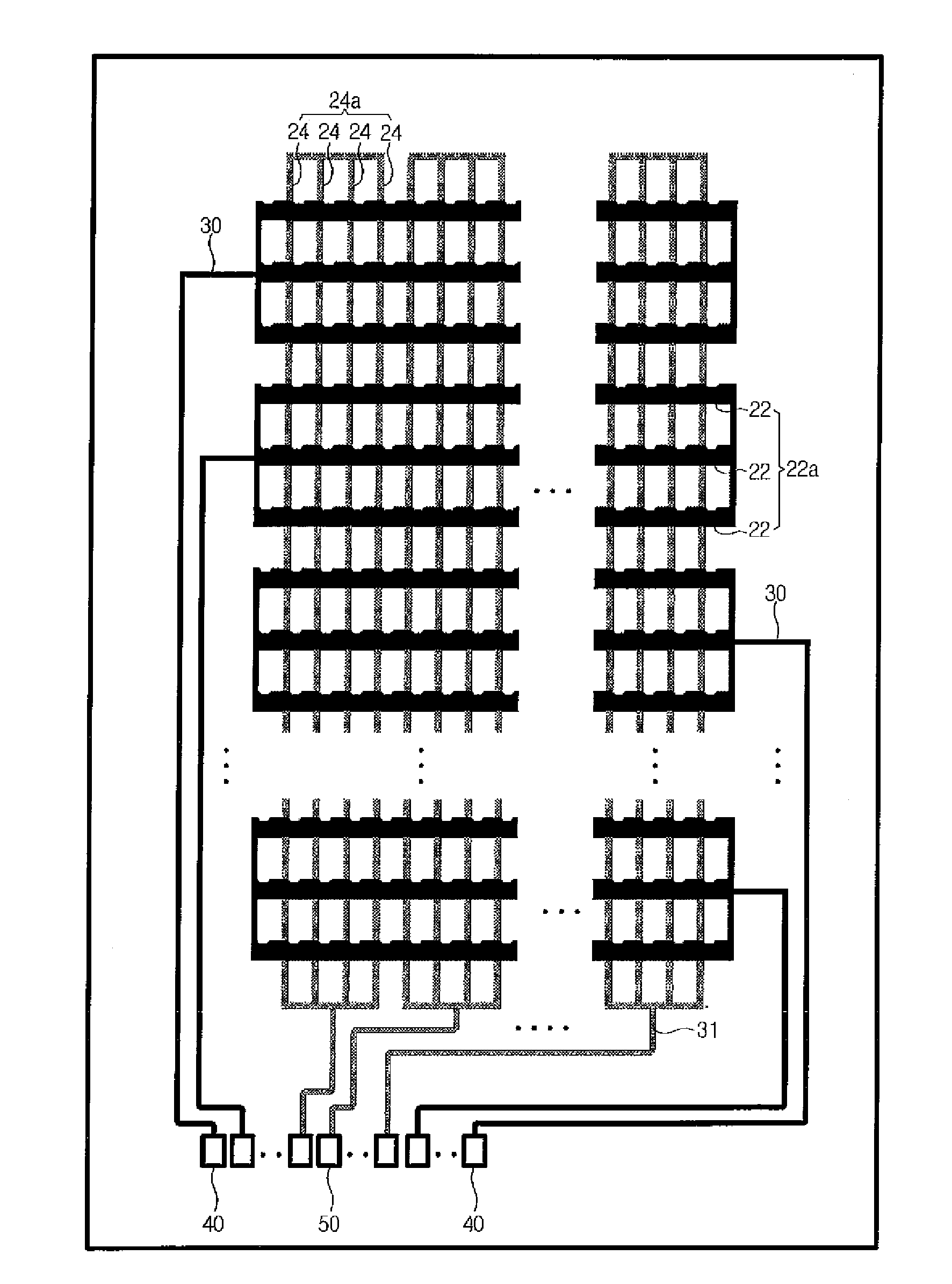
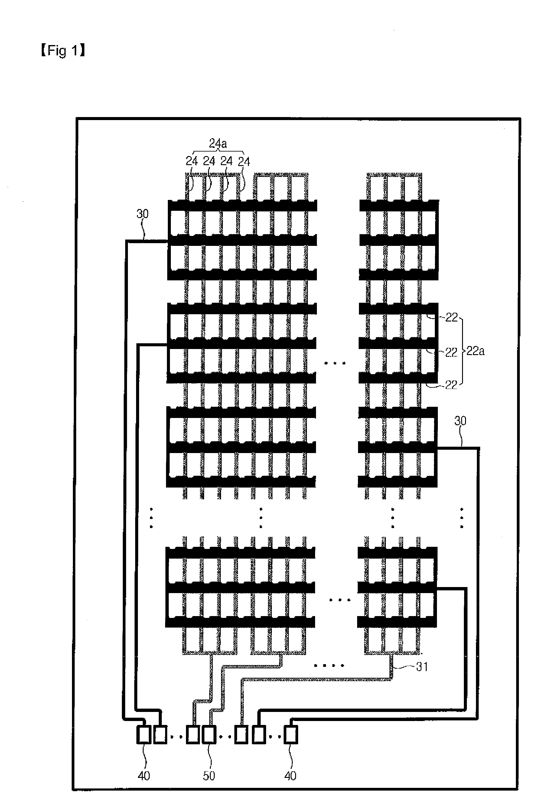
[0016]Accordingly, the present invention is conceived to solve the forgoing problems, and an aspect of the present invention is to provide an LCD apparatus with a built-in touch sensor, in which a touch signal line usable as a light shielding member for shielding light and a signal line for sensing touch is formed at a position for a conventional black matrix, thereby enhancing transmittance and simplifying a process.

Problems solved by technology

Accordingly, there are shortcomings that accuracy is deteriorated, detection speed becomes lowered, and it is impossible to detect touches at different positions.
Further, because the substrate is frequently deformed by the press, there is a problem of low durability.
However, even the capacitive type has a structure where one of the two opposite substrates additionally includes a sensing electrode in X and Y axial direction, and thus there is a problem that transmittance of the LCD apparatus is remarkably lowered.
Also, a touch panel is manufactured separately from the LCD apparatus, and thus there are problems of difficulty in a process, increase in production cost, etc.
Further, such a structure increases the thickness of the LCD apparatus, and thus there is a limit to make the LCD apparatus thin.

Method used


Image

  • Liquid Crystal Display Apparatus with In Touch Sensor and Manufacturing Method Thereof
  • Liquid Crystal Display Apparatus with In Touch Sensor and Manufacturing Method Thereof
  • Liquid Crystal Display Apparatus with In Touch Sensor and Manufacturing Method Thereof

Examples


Embodiment Construction

[0038]Prior to description, elements will be representatively explained in an embodiment and only different configurations will be described in another embodiment, in which like reference numerals refer to like elements throughout.

[0039]Hereinafter, a liquid crystal display (LCD) apparatus with a built-in touch sensor according to a first exemplary embodiment of the present invention will be described with reference to the accompanying drawings.

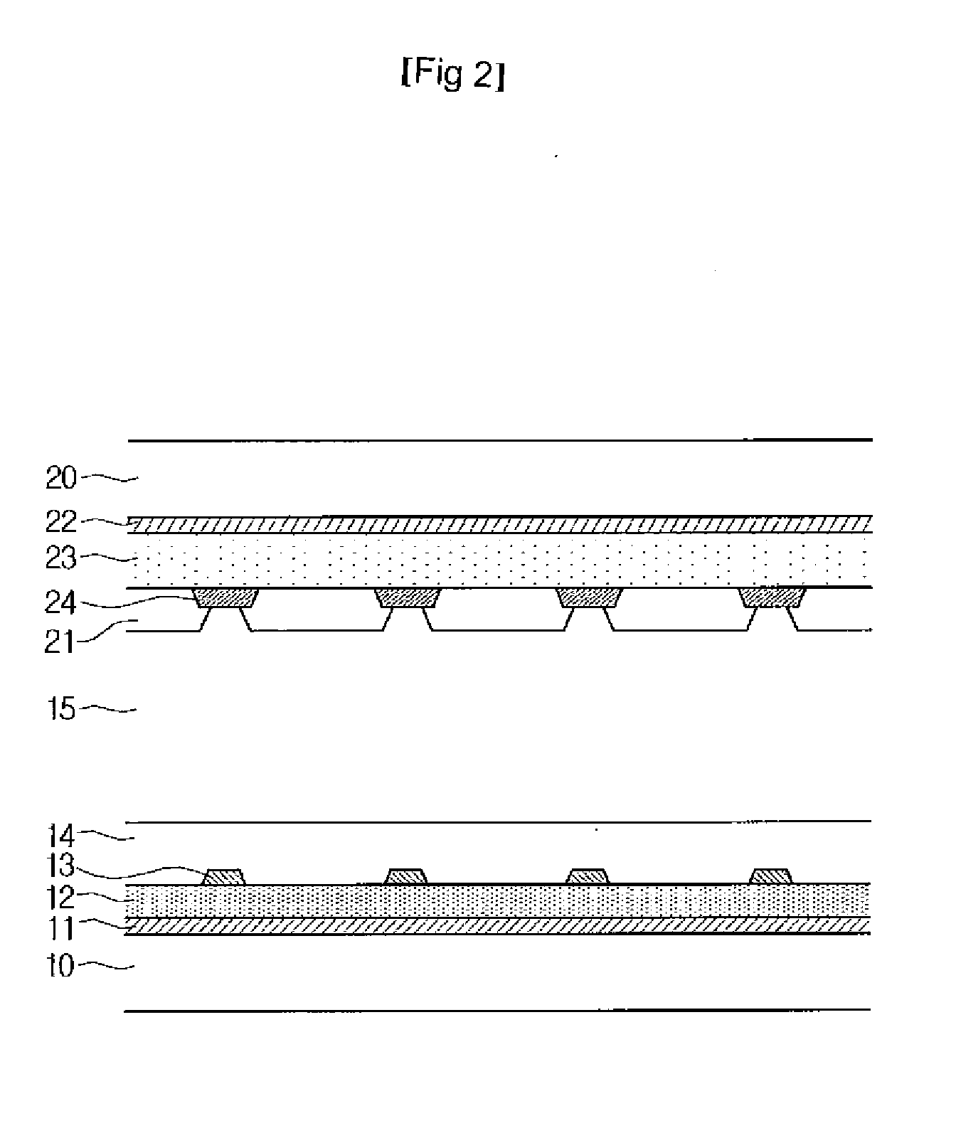
[0040]FIG. 1 is a schematic view of an LCD apparatus with a built-in touch sensor according to a first exemplary embodiment of the present invention, FIG. 2 is a cross-section view taken along a second touch signal line in FIG. 1, and FIG. 3 is a cross-section view taken along a first touch signal line in FIG. 1.

[0041]Referring to FIGS. 1 to 3, the LCD apparatus with the built-in touch sensor according to the first exemplary embodiment of the present invention includes a first substrate 10, an second substrate 20 opposite to the first substra...


PUM


Abstract

Disclosed is a liquid crystal display (LCD) apparatus with a built-in touch sensor, the LCD apparatus including: a first substrate and a second substrate placed facing each other with a liquid crystal layer interposed therebetween; a plurality of gate lines and a plurality of data lines arranged to intersect each other and defined a pixel region on the first substrate; a plurality of first touch signal lines formed on a surface of the second substrate opposite to the first substrate substantially corresponding to the respective gate lines; a plurality of second touch signal lines formed on the surface of the second substrate substantially corresponding to the respective data lines while being insulated from and intersecting with the first touch signal lines; and a color filter formed on the surface of the second substrate substantially corresponding to the pixel region, wherein the first touch signal lines and the second touch signal lines serve as a signal line for sensing touch as well as a light shielding member.

Description

CROSS-REFERENCE TO RELATED APPLICATION[0001]This application claims priority to and the benefit of Korean Patent Application No. 10-2011-0027544 filed in the Korean Intellectual Property Office on Mar. 28, 2011, the entire contents of which are incorporated herein by reference.BACKGROUND OF THE INVENTION[0002](a) Field of the Invention[0003]The present invention relates to a liquid crystal display (LCD) apparatus with a built-in touch sensor, and more particularly, to an LCD apparatus with a built-in touch sensor, in which sensing lines are formed at a position for a conventional black matrix formed in a light shielding region and serve as both a light shielding member and a touch sensor to improve transmittance.[0004](b) Description of the Related Art[0005]Generally, an LCD apparatus is a display apparatus in which liquid crystal is injected as an intermediated material between solid and liquid into a space between two substrates, and an effect of light and shadow is generated to d...

Claims


Application Information

Patent Timeline
IPC IPC(8): G06F3/041H01J9/00
CPCG02F1/13338G06F3/0412G06F3/0446G06F2203/04103G06F3/0448
Inventor CHOI, JIN WOOKYOON, HYOUNG JIN
Owner HYDIS TECH
Learn More