
Angiography system for angiographic examination of an object under examination and angiographic examination method

a technology of angiography and object, applied in the field of angiography system for angiographic examination and angiographic examination method, can solve the problems of troublesome navigation of guidewire into the narrow opening of the main sten

Active Publication Date: 2012-10-04
SIEMENS HEALTHCARE GMBH
View PDF2 Cites 17 Cited by
  • Summary
  • Abstract
  • Description
  • Claims
  • Application Information

AI Technical Summary

Benefits of technology

[0024]This results in the user being provided in a simple manner with an automatically pre-selectable angulation, which makes it easier to see important details in the x-ray image since they are not hidden by other details for example.
[0032]It has proved advantageous for the 3D dataset of the object under examination to be a pre-operative CT, MR angiography registered to the C-arm or an intra-operative rotation angiography to show soft tissue.
[0046]It has proved advantageous for the angulation calculated in accordance with step S6) to be transferred to the C-arm automatically or at the touch of a button.
[0048]In an advantageous manner the angulation of the C-arm sought can lie both at right angles to the main axis and also at right angles to the connecting axis between two openings of the object under examination.

Problems solved by technology

Above all the navigation of the guidewire into the narrow opening of the main stent can be problematic, since the two openings are not always aligned in parallel to the observer.

Method used


Image

  • Angiography system for angiographic examination of an object under examination and angiographic examination method
  • Angiography system for angiographic examination of an object under examination and angiographic examination method
  • Angiography system for angiographic examination of an object under examination and angiographic examination method

Examples


Embodiment Construction

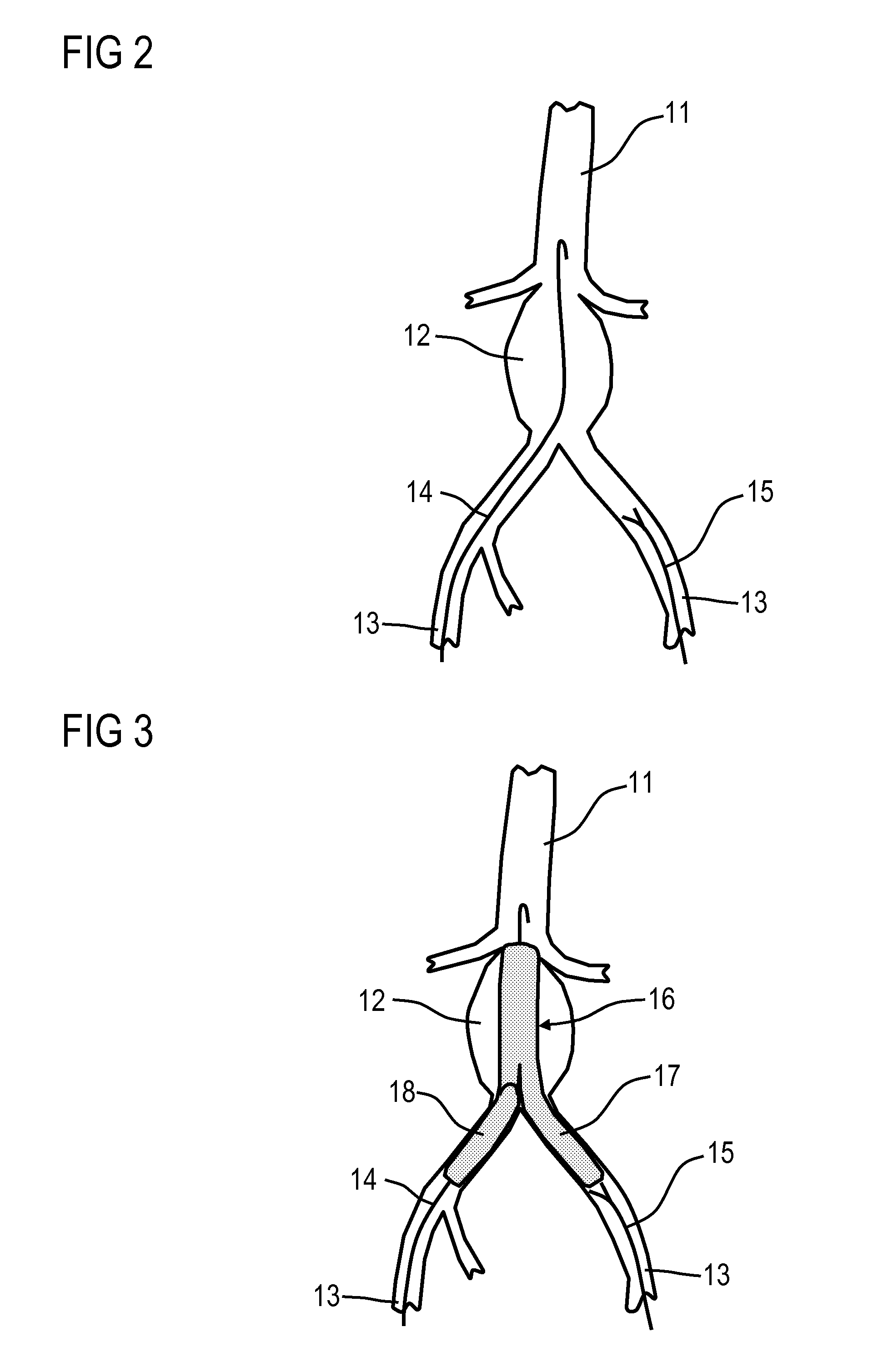
[0059]Shown in FIG. 2 is an abdominal aorta 11 having an abdominal aortic aneurysm (AAA) 12. An abdominal aortic aneurysm (AAA) 12 is an aneurysm on the abdominal aorta 11.

[0060]The aortic aneurysm 12 is treated by insertion of a stent graft, i.e. a plastic vessel, as is shown in FIG. 3. To do this, guidewires 14 and catheters 15 are introduced into the aorta via the two groins through the leg arteries 13, via which the stent grafts 16 are introduced.

[0061]With complex stent grafts 16, which also include the leg arteries 13, the final stent must sometimes be assembled from “part stents”, wherein for example at an aorta stent as main stent 17, which extends through the AAA into one of the leg arteries 13, a part stent 18 for the other leg artery 13 is “flanged on” through what is referred to as a window.

[0062]After the main stent 17 has been introduced, as is shown in FIG. 4, a guidewire 14 is introduced through a stent opening 19 in the main stent 17. The part stent 18 (not shown in...


PUM


Abstract

An angiography system for angiographic examination or treatment of an organ, vascular system or other regions of an object of a patient is proposed. The system has an x-ray source and an x-ray image detector disposed at ends of a C-arm, a patient support table, a system control unit, an image system, and a monitor. The object contains two details hiding each other in the x-ray images depending on angulation of the C-arm. The system control unit has a device that detects a 3D dataset of the object registered to the C-arm and detects the information about a course of the object. The device calculates a desired and / or optimum angulation of the C-arm from the detected information and transfers the calculated angulation to the system control unit for adjusting the C-arm to the angulation.

Description

CROSS REFERENCE TO RELATED APPLICATIONS[0001]This application claims priority of German application No. 10 2011 006 484.2 filed Mar. 31, 2011, which is incorporated by reference herein in its entirety.FIELD OF INVENTION[0002]The invention relates to an angiography system for angiographic examination or treatment of an organ, vascular system or other regions of the body of a patient as the object under examination.BACKGROUND OF INVENTION[0003]An angiography system of this type is known for example from U.S. Pat. No. 7,500,784 B2, and said system is explained below with reference to FIG. 1.[0004]FIG. 1 shows a monoplane x-ray system presented by way of example with a C-arm 2 in the form of a six-axis industrial or articulated-arm robot supported by a stand 1, to the ends of which an x-radiation source, for example an x-ray emitter 3 with x-ray tube and collimator and an x-ray image detector 4 as an image recording unit are attached.[0005]By means of the articulated-arm robot known fro...

Claims


Application Information

Patent Timeline
IPC IPC(8): G06K9/00A61B6/03
CPCA61B6/12A61B6/4441A61B6/4458A61B6/487A61B6/504A61B6/481
Inventor PFISTER, MARCUS
Owner SIEMENS HEALTHCARE GMBH
Learn More