Hand operated vibratory machine with vibration dampening handle mount

a technology of vibration dampening handle and vibratory machine, which is applied in the direction of machine support, roads, highways, etc., can solve the problems of long curing time, uneven or inconsistence, labor-intensive manual wet screeding process, etc., and achieve the effect of reducing the transmission of undesirable vibrations to the machine's handles

Inactive Publication Date: 2012-10-04
WACKER NEUSON PRODN AMERICAS
View PDF3 Cites 12 Cited by
  • Summary
  • Abstract
  • Description
  • Claims
  • Application Information

AI Technical Summary

Benefits of technology

[0010]One or more of the above-identified needs are met by providing an improved handle mount for use in a vibratory machine that reduces the transmission undesirable vibrations to the machine

Problems solved by technology

This manual wet screeding process is labor intensive, requiring at least two individuals positioned at opposite ends to drag the screeding board.
Furthermore, this manual approach is time consuming, physically fatiguing, and often results in uneven or inconsistence results, due in part to the lack of vibration imparted onto the wet concrete surface.
However, increasing the water component results in both prolonged curing times as well as increases the presence of voids or weaknesses within the resulting cured concrete slab.
However, operation of vibratory wet screed machines presents drawbacks of

Method used


Image

  • Hand operated vibratory machine with vibration dampening handle mount
  • Hand operated vibratory machine with vibration dampening handle mount
  • Hand operated vibratory machine with vibration dampening handle mount

Examples


Embodiment Construction

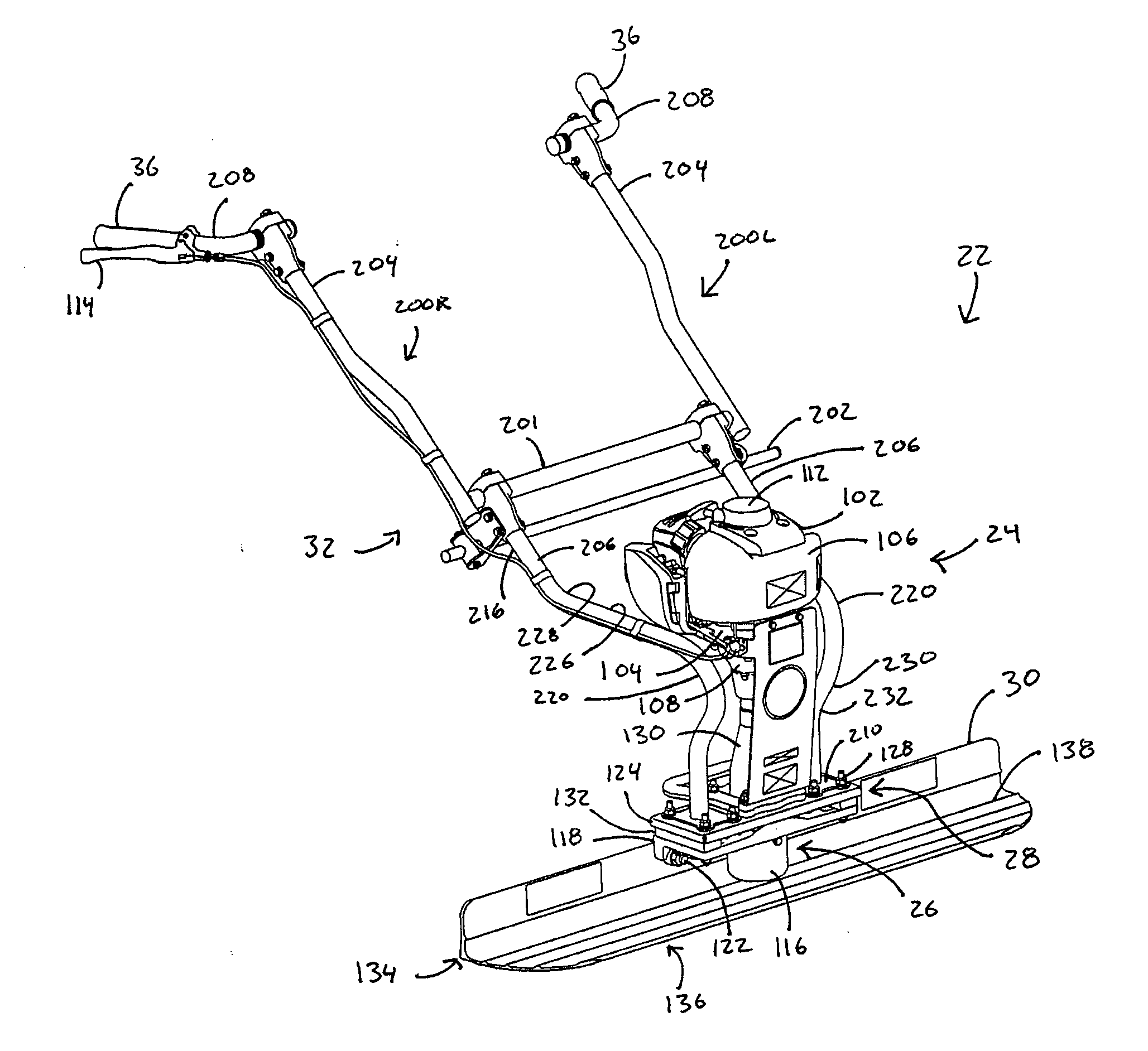
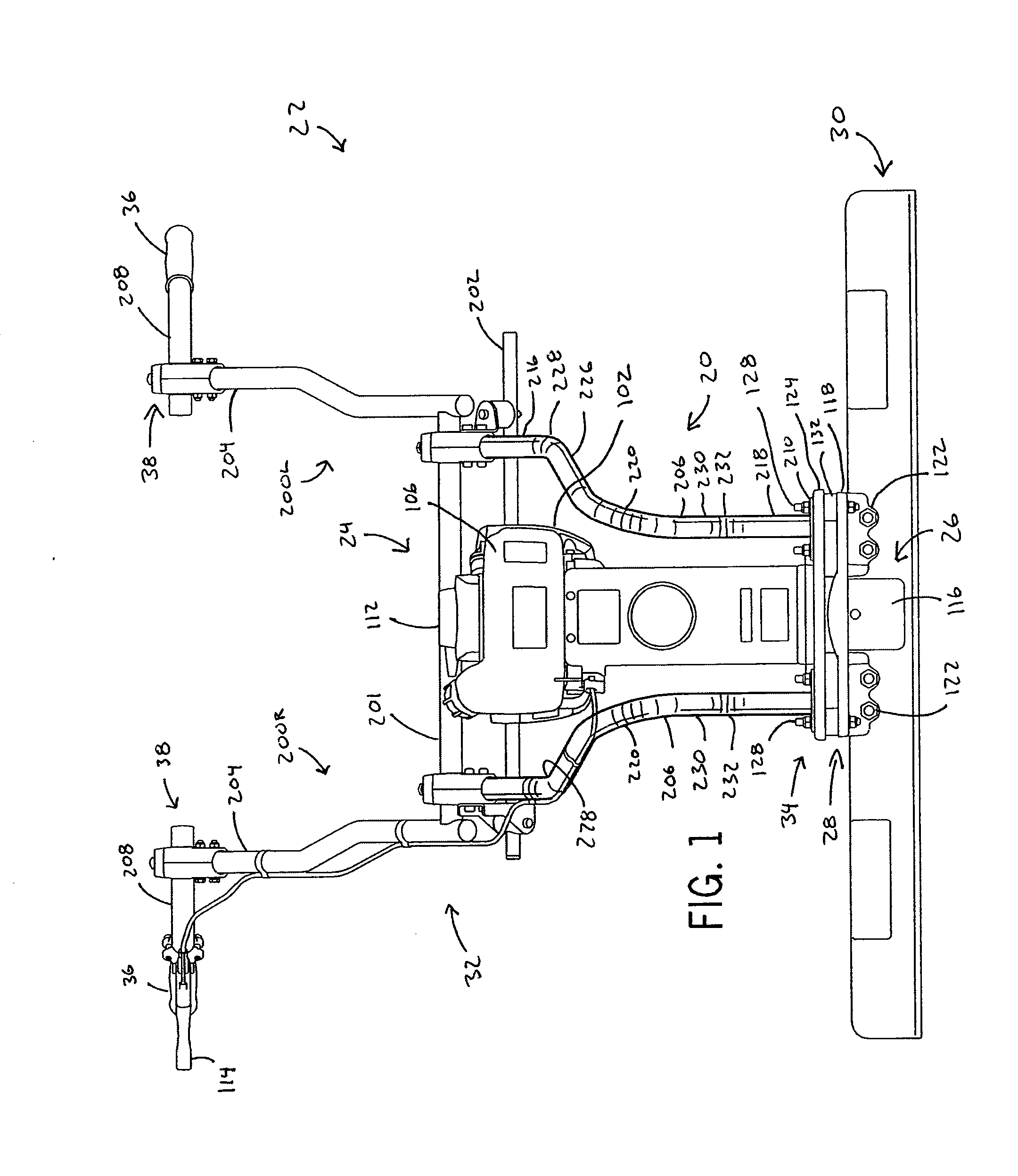
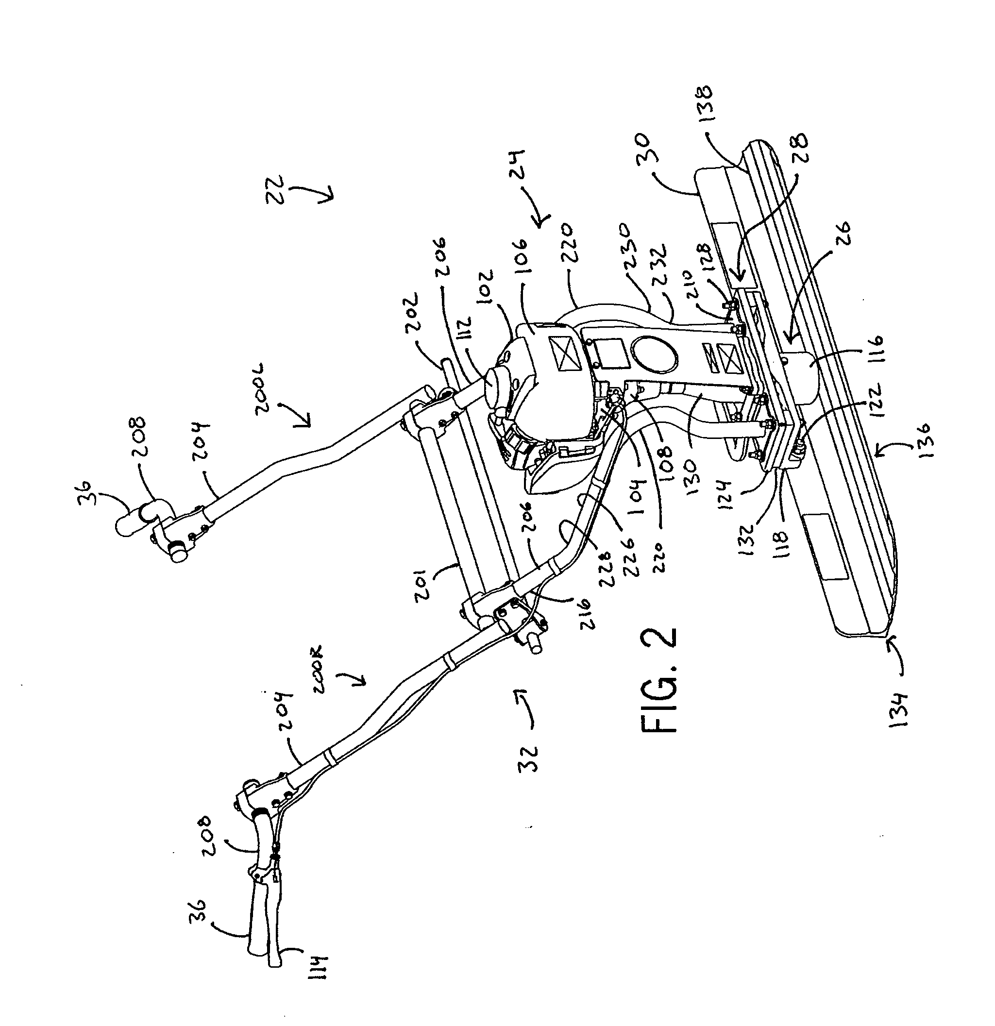
[0026]A wide variety of handle mounts for vibrating hand operated machines could be constructed in accordance with the invention as defined by the claims. Hence, while the preferred embodiments of the invention will now be described with reference to a portable vibratory wet screed machine, it should be understood that the invention is in no way so limited. For instance, it is also usable with a variety of different portable vibratory machines that are potentially subject to undesired vibration transmission through the handle.

[0027]FIG. 1 illustrates a front plan view of a handle 20 constructed in accordance with one embodiment of the invention. Generally, the vibratory wet screed machine 22 includes an engine 24 coupled to a vibration generator 26. The vibration generator 26 typically includes an eccentric mass that is driven to rotate by an output shaft of the engine 24. The engine 24 and vibration generator 26 are mounted on a frame 28 located at a center of an elongated blade 30...


PUM


Abstract

A vibration generating machine and method of use is provided. The vibration generating machine includes a work piece such as screed blade and a vibration generator for imparting vibrations to the work piece. The machine is guided by a handle mounted on the work piece by a monolithic handle mount. The monolithic handle mount includes a lower section for mounting directly or indirectly to the work piece, an upper section at least indirectly supporting a handgrip, and an intermediate section having a partial coil that reduce the transmission of vibrations therethrough.

Description

BACKGROUND OF THE INVENTION[0001]1. Field of the Invention[0002]The invention relates generally to hand guided vibratory machines and, more particularly, relates to a vibratory machine with monolithic handle mount that reduces the transmission of vibrations to the operator. The invention additionally relates to a method of operating such a machine.[0003]2. Discussion of the Related Art[0004]Many hand guided machines employ vibratory action. Examples of such machine include vibratory plates or tampers for compacting soil and vibratory wet screeds for leveling and smoothing freshly poured concrete. While these various machines may differ in purpose and function, they all employ a vibratory generator to impart vibrations to a work piece such as a ground-engaging plate or shoe or a concrete-engaging blade.[0005]One specific example of a known hand guided vibratory machine is a vibratory wet screed. The vibratory wet screed employs an elongated blade that extends over a surface of freshl...

Claims


Application Information

Patent Timeline
IPC IPC(8): E01C19/38F16F15/04
CPCE04F21/242E01C19/40E01C19/402E04G21/10
Inventor SPERFSLAGE, TANDREA
Owner WACKER NEUSON PRODN AMERICAS
Why Eureka
Try Eureka