Vibration determination method and vibration determination device

a vibration determination and vibration technology, applied in the direction of process and machine control, program control, instruments, etc., can solve the problems of reducing the finishing accuracy of a processed surface, causing so-called “chatter vibrations, and breaking tools, etc., to achieve more reliably suppressed chatter vibration and regenerative chatter vibration. , the effect of determining the accuracy of regenerative chatter vibration

Active Publication Date: 2012-10-04
OKUMA CORP
View PDF3 Cites 27 Cited by
  • Summary
  • Abstract
  • Description
  • Claims
  • Application Information

AI Technical Summary

Benefits of technology

[0031]According to the present invention, when generation of a chatter vibration is detected, the parameter calculation device calculates the first frequency range and the second frequency range. The determination validity is calculated based on the ratio of the frequency range of rotational-period forced chatter vibration to the frequency range of regenerative chatter vibration. It is determined based on the determination validity whether the generated chatter vibration is regenerative chatter vibration, rotational-period forced chatter vibration, or flute-passage-period forced chatter vibration. According to the second aspect of the present invention, in particular, the rotation speed detection resolution AS and the frequency resolution Δf are also taken into consideration. Therefore, it is possible to determine regenerative chatter vibration and forced chatter vibration more accurately than the related art, and to detect rotational-period forced chatter vibration that could not be detected by the related art. Thus, chatter vibration can be more reliably suppressed.
[0032]According to the fourth aspect of the present invention, the vibration determination device includes the display device that displays the determined type of the chatter vibration. This allows an operator to easily know the type of chatter vibration generated, and to immediately take effective countermeasures for that particular type of chatter vibration. Thus, the chatter vibration can be suppressed in a short time to minimize a reduction in the finishing accuracy of a processed surface, tool wear, and so forth.

Problems solved by technology

A machine tool that performs processing by rotating a rotary shaft may generate a so-called “chatter vibration” during processing when processing conditions such as the depth of cut and the rotation speed of the rotary shaft are inappropriate.
Chatter vibration may reduce the finishing accuracy of a processed surface, and may break the tool.
Therefore, under such processing conditions, regenerative chatter vibration with a phase difference ε of close to zero may be erroneously determined as forced chatter vibration.
The detection accuracy of vibration acceleration and rotation speed is limited, and inevitably subjected to error.
That is, forced chatter vibration may be erroneously determined as regenerative chatter vibration.

Method used


Image

  • Vibration determination method and vibration determination device
  • Vibration determination method and vibration determination device
  • Vibration determination method and vibration determination device

Examples


Embodiment Construction

[0039]A vibration determination method, and a vibration suppressing device that includes a vibration determination device according to an embodiment of the present invention will be described in detail below with reference to the drawings.

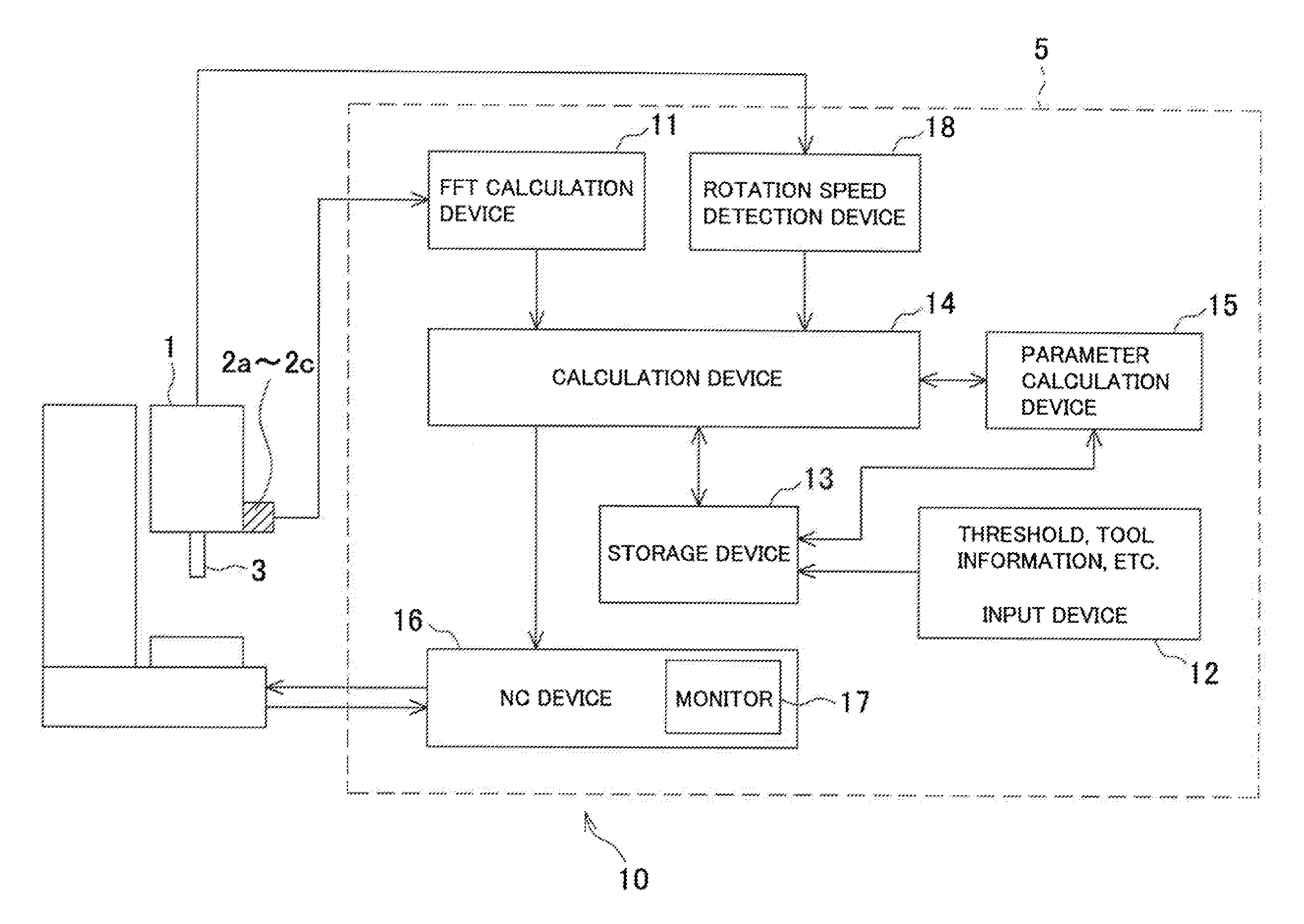
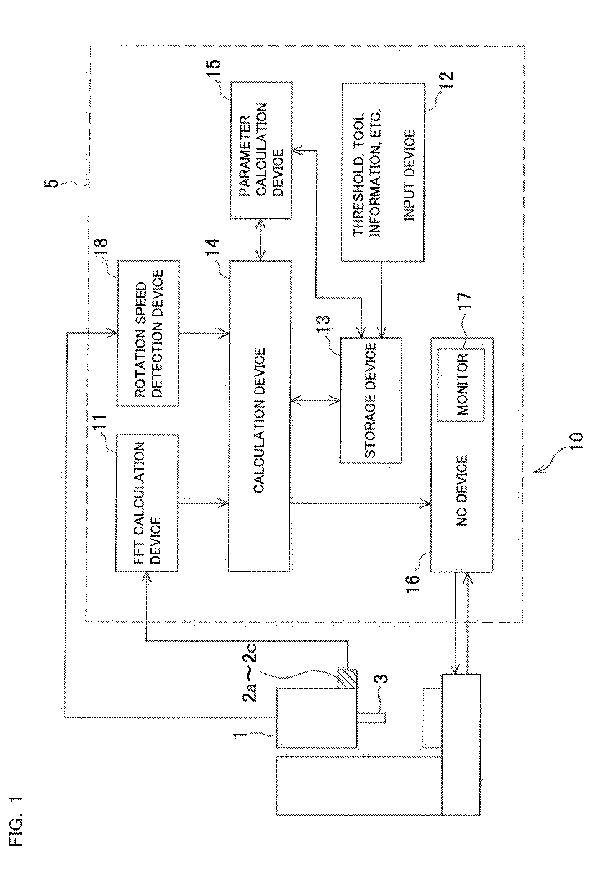
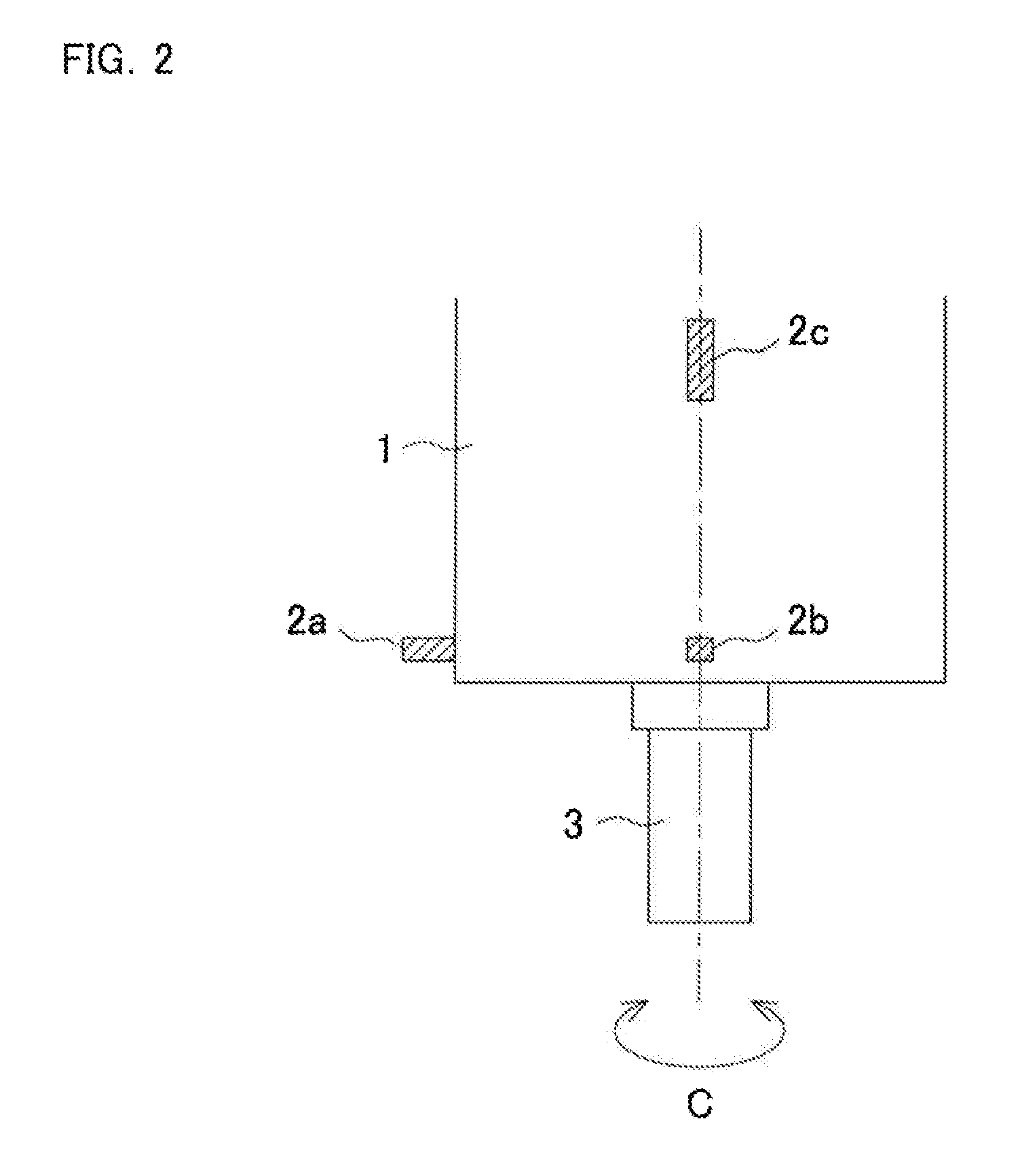
[0040]FIG. 1 is a block diagram that shows a vibration suppressing device 10. FIG. 2 is a diagram that shows a rotary shaft housing 1 subject to vibration suppression as seen from a side. FIG. 3 is a diagram that shows the rotary shaft housing 1 as seen from the axial direction.

[0041]The vibration suppressing device 10 suppresses a “chatter vibration” generated by a rotary shaft 3 provided in the rotary shaft housing 1 as rotatable about an axis C. The vibration suppressing device 10 includes vibration sensors 2a to 2c and a control device 5. The vibration sensors 2a to 2c detect a time-domain vibration acceleration (which means vibration acceleration on a time axis), which is a characteristic value related to the vibration generated by the rotary ...


PUM


Abstract

When generation of a chatter vibration is detected, a parameter calculation device calculates a first frequency range and a second frequency range. A determination validity is calculated in consideration of a rotation speed detection resolution and a frequency resolution, and based on a ratio of a frequency range of rotational-period forced chatter vibration to a frequency range of regenerative chatter vibration. It is determined based on the determination validity whether the generated chatter vibration is regenerative chatter vibration, rotational-period forced chatter vibration, or flute-passage-period forced chatter vibration.

Description

BACKGROUND OF INVENTION[0001]This application claims the benefit of Japanese Patent Application Number 2011-070445 filed on Mar. 28, 2011, the entirety of which is incorporated by reference.TECHNICAL FIELD[0002]The present invention relates to a vibration determination method for determining a type of chatter vibration generated in a machine tool during processing performed by rotating a tool or a workpiece, and to a vibration determination device that executes the vibration determination method.BACKGROUND ART[0003]A machine tool that performs processing by rotating a rotary shaft may generate a so-called “chatter vibration” during processing when processing conditions such as the depth of cut and the rotation speed of the rotary shaft are inappropriate. Chatter vibration may reduce the finishing accuracy of a processed surface, and may break the tool. Thus, it is desired to suppress chatter vibration.[0004]There are two types of chatter vibration, namely, a “regenerative chatter vi...

Claims


Application Information

Patent Timeline
Patent Type & Authority Applications(United States)
IPC IPC(8): G06F19/00
CPCB23Q11/0039G05B2219/41256G05B19/404B23Q17/12
Inventor TANAKA, TAKAAKI
Owner OKUMA CORP
Why Eureka
Try Eureka