Electromechanical transducer and method of producing the same
a technology of electromechanical transducers and transducers, which is applied in the direction of piezoelectric/electrostrictive transducers, mechanical vibration separation, generators/motors, etc., can solve the problems of vibration film breaking in some cases, silicon oxide film compression stress,
- Summary
- Abstract
- Description
- Claims
- Application Information
AI Technical Summary
Benefits of technology
Problems solved by technology
Method used
Image

Examples
example 1
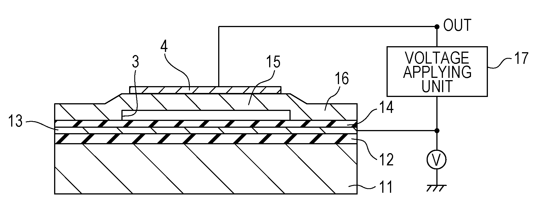
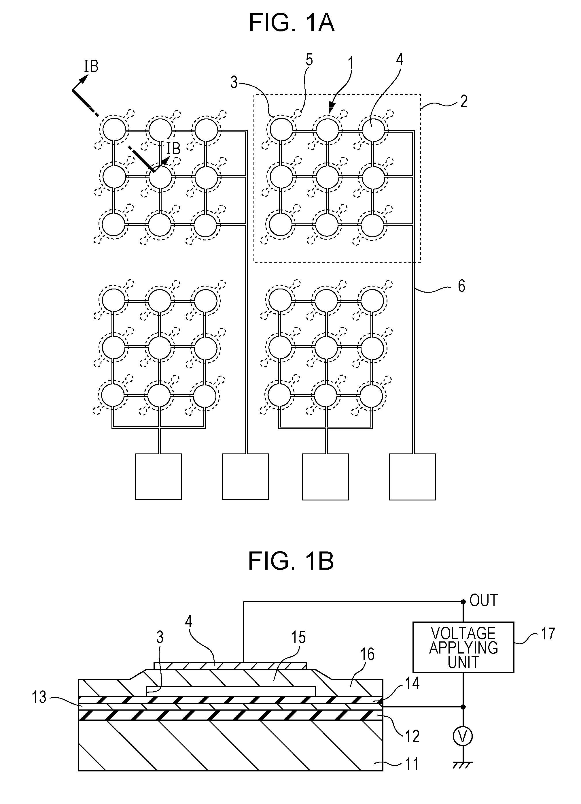
[0050]The configuration of the electromechanical transducer of Example 1 according to aspects of the present invention will be described with reference to FIGS. 1A and 1B. FIG. 1A is a top view illustrating an electromechanical transducer, and FIG. 1B is a cross-sectional view taken along line IB-IB of FIG. 1A.
[0051]A cell structure 1 includes a silicon substrate 11 having a thickness of 300 μm, a first insulating film 12 disposed on the silicon substrate 11, a first electrode 13 disposed on the first insulating film 12, and a second insulating film 14 on the first electrode 13. The cell structure 1 further includes a vibration film composed of a membrane 15 and a second electrode 4 disposed on the membrane 15, wherein the membrane 15 is disposed on the second insulating film 14 with a cavity 3 therebetween; and a membrane-supporting portion 16 supporting the membrane 15. A voltage is applied between the first electrode 13 and the second electrode 4 with a voltage-applying unit.
[005...
example 2
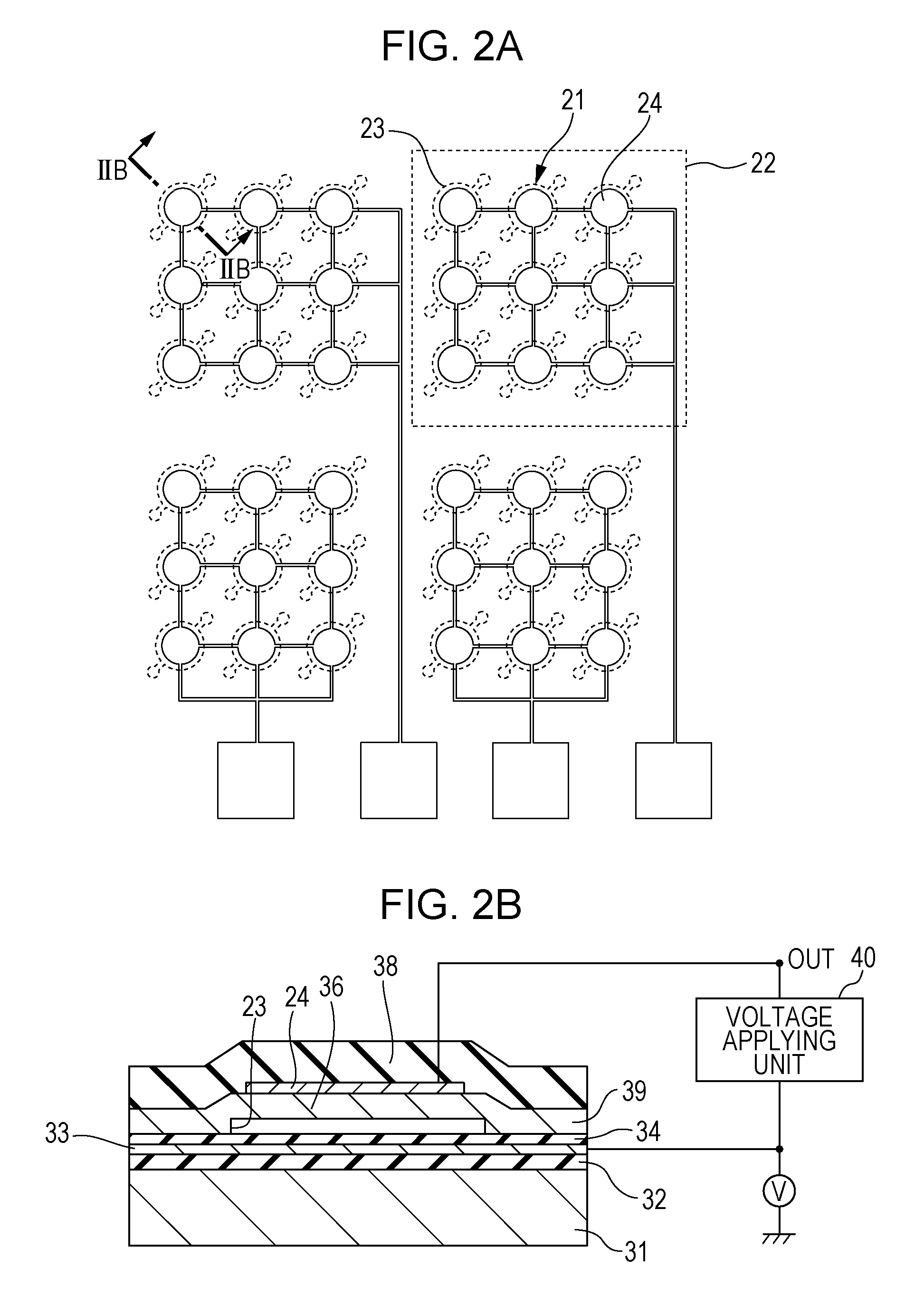
[0058]The configuration of the electromechanical transducer of Example 2 according to aspects of one embodiment will be described with reference to FIGS. 2A and 2B. The configuration of the electromechanical transducer shown in FIGS. 2A and 2B is different from that in Example 1 in that the vibration film has a three-layer structure. FIG. 2A is a top view illustrating the electromechanical transducer according to aspects of one embodiment, and FIG. 2B is a cross-sectional view taken along line IIB-IIB of FIG. 2A.
[0059]The cell structure 21 of this Example includes a silicon substrate 31 having a thickness of 300 μm, a first insulating film 32 disposed on the silicon substrate 31, a first electrode 33 disposed on the first insulating film 32, and a second insulating film 34 on the first electrode 33. The cell structure 21 further includes a vibration film, composed of a first membrane 36, a second membrane 38, and a second electrode 24, disposed on the second insulating film 34 with ...
example 3
[0066]Example 3 according to aspects of one embodiment will be described. This Example relates to a method of producing an electromechanical transducer. The method of the present invention will be described with reference to FIGS. 3 and 4A to 4F. FIG. 3 is a top view of an electromechanical transducer of the present invention, and FIGS. 4A to 4F are cross-sectional views taken along line IV-IV of FIG. 3.
[0067]As shown in FIG. 4A, a first insulating film 51 is formed on a substrate 50. The substrate 50 is a silicon substrate having a thickness of 300 μm. The first insulating film 51 is a silicon oxide film having a thickness of 1 μm formed by thermal oxidation for providing insulation between the first electrode 52 and the substrate 50.
[0068]Subsequently, as shown in FIG. 4B, a first electrode 52 is formed. The first electrode 52 is made of titanium and has a thickness of 50 nm and a root mean surface roughness (Rms) of 2 nm or less. The first electrode 52 may be formed by sputtering...
PUM
| Property | Measurement | Unit |
|---|---|---|
| tensile stress | aaaaa | aaaaa |
| tensile stress | aaaaa | aaaaa |
| electric field intensity | aaaaa | aaaaa |
Abstract
Description
Claims
Application Information
 - R&D Engineer
- R&D Manager
- IP Professional
- Industry Leading Data Capabilities
- Powerful AI technology
- Patent DNA Extraction
Browse by: Latest US Patents, China's latest patents, Technical Efficacy Thesaurus, Application Domain, Technology Topic.
© 2024 PatSnap. All rights reserved.Legal|Privacy policy|Modern Slavery Act Transparency Statement|Sitemap