System for scanning, mapping and measuring conduits

a mapping and conduit technology, applied in the field of scanning, mapping and measuring conduits, can solve the problems of not providing meaningful information on the size (or diameter) of the conduit along its length, unable to run two inspection passes at the same time, and the raw unprocessed video footage captured by the closed circuit camera may not be very useful on its own, so as to achieve sufficient quality and lessen the contrast of the visible light contour

Inactive Publication Date: 2012-10-11
FER PAL CONSTR
View PDF7 Cites 78 Cited by
  • Summary
  • Abstract
  • Description
  • Claims
  • Application Information

AI Technical Summary

Benefits of technology

[0016]According to a broad aspect of an embodiment of the present invention, there is provided a system for scanning, mapping and measuring conduits. The system includes a data collection subsystem having a carriage assembly sized to fit within a conduit for travel therethrough and equipment module supported on the carriage assembly. The equipment module includes a housing, a video capture system and a lighting assembly accommodated within the housing, and a laser beam emitting and diffusion assembly attached to the housing forwardly of the video capture system. The laser beam emitting and diffusion assembly is operable to emit a laser beam and diffuse the laser beam along a plane P substantially perpendicular to the laser beam so as to trace a visible light contour where the plane P intersects the inner surface of the conduit. The laser beam is a light of a first colour. The video capture system is operable to record images of the conduit and the visible light contour generated by the laser beam emitting and diffusion assembly. The lighting assembly includes at least one LED light capable of emitting light of a second colour. The light of the second colour is different than the light of the first colour. The light of the second colour is selected so as provide sufficient illumination within the conduit to reveal features of the conduit when the at least one LED light is activated, while not substantially lessening the contrast of the visible light contour against the dark background formed by the conduit thereby allowing the images of the visible light contour of a sufficient quality to be captured for further processing. The system is further provided with a data processing subsystem that is in data communication with the data collection subsystem. The data processing subsystem being operable to process the images of the conduit and the visible light contour and to generate therefrom digital views of the conduit.

Problems solved by technology

These systems do not appear to provide any meaningful information on the size (or diameter) of the conduit along its length.
Under such operating conditions, the raw unprocessed video footage captured by the closed circuit camera may not be very useful on its own, since internal details of the pipe may not be clearly visible due to the low light conditions.
Running two inspection passes tends not to be advantageous because it doubles the inspection time for each pipe.
Moreover, it can create data correlation issues when data from the first inspection pass is merged with data from the second inspection pass.

Method used


Image

  • System for scanning, mapping and measuring conduits
  • System for scanning, mapping and measuring conduits
  • System for scanning, mapping and measuring conduits

Examples


Embodiment Construction

[0053]The description, which follows, and the embodiments described therein are provided by way of illustration of an example, or examples of particular embodiments of principles and aspects of the present invention. These examples are provided for the purposes of explanation and not of limitation, of those principles of the invention. In the description that follows, like parts are marked throughout the specification and the drawings with the same respective reference numerals.

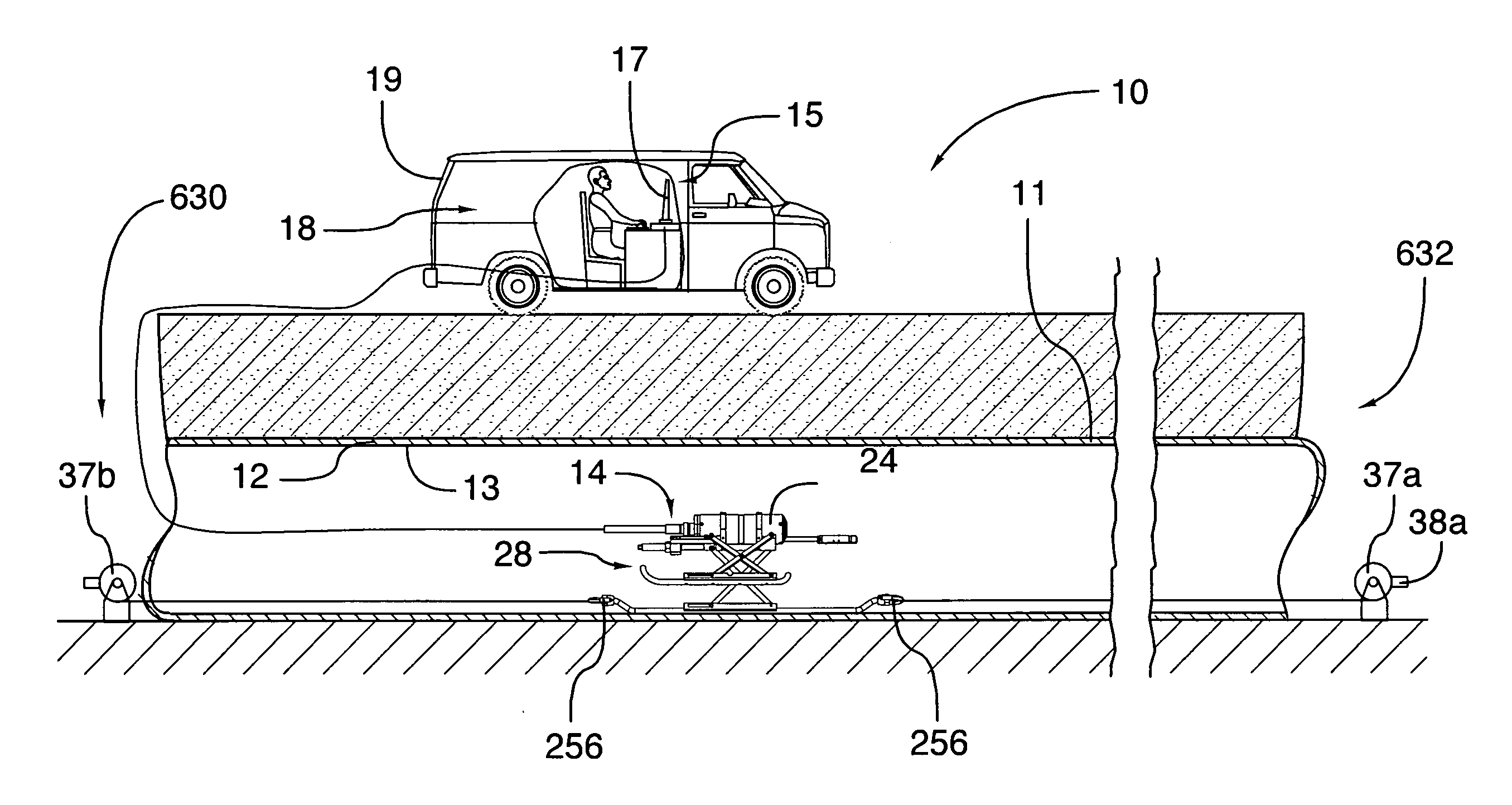
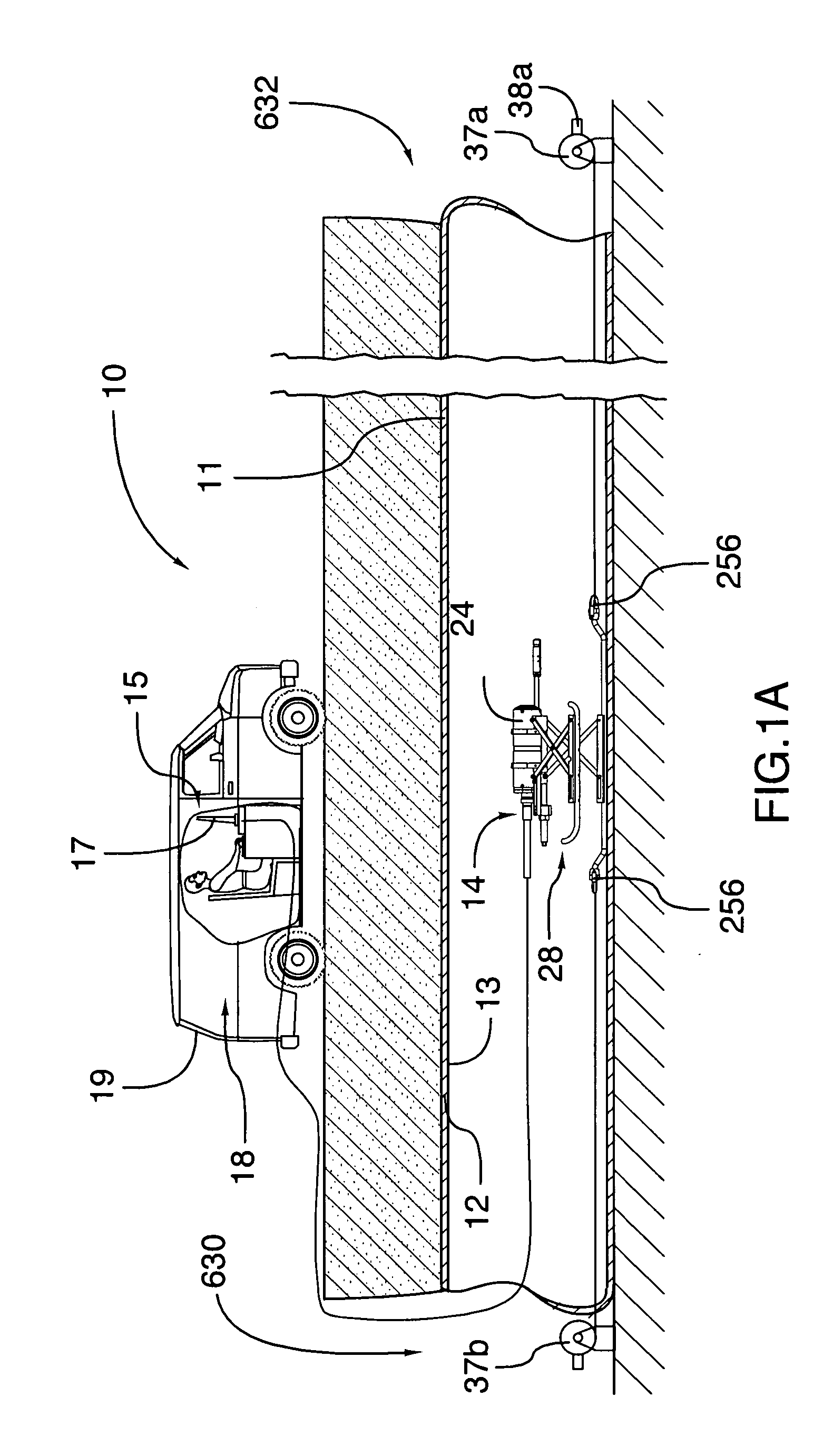
[0054]Referring to FIG. 1a, there is shown conceptually a system for scanning, mapping and measuring conduits designated generally with reference numeral 10. The system 10 is designed for deployment in a conduit 11 having a generally tubular configuration defined by a conduit wall 12 provided with an inner surface 13. In this embodiment, the conduit 11 is a municipal conduit which runs below ground and forms part of a network of water works conduits delivering potable water to residents of a neighbourhood via...


PUM


Abstract

The present invention relates to a system for scanning, mapping and measuring conduits. The system includes a data collection subsystem having a carriage assembly sized to fit within a conduit for travel therethrough and equipment module supported on the carriage assembly. The equipment module includes a housing, a video capture system and a lighting assembly accommodated within the housing, and a laser beam emitting and diffusion assembly attached to the housing forwardly of the video capture system. The laser beam emitting and diffusion assembly is operable to emit a laser beam and diffuse the laser beam along a plane P substantially perpendicular to the laser beam so as to trace a visible light contour where the plane P intersects the inner surface of the conduit. The laser beam is a light of a first colour. The video capture system is operable to record images of the conduit and the visible light contour generated by the laser beam emitting and diffusion assembly. The lighting assembly includes at least one LED light capable of emitting light of a second colour. The light of the second colour is different than the light of the first colour. The light of the second colour is selected so as provide sufficient illumination within the conduit to reveal features of the conduit when the at least one LED light is activated, while not substantially lessening the contrast of the visible light contour against the dark background formed by the conduit thereby allowing the images of the visible light contour of a sufficient quality to be captured for further processing. The system is further provided with a data processing subsystem that is in data communication with the data collection subsystem. The data processing subsystem being operable to process the images of the conduit and the visible light contour and to generate therefrom digital views of the conduit.

Description

FIELD OF THE INVENTION[0001]The present invention relates to a system for scanning, mapping and measuring conduits.BACKGROUND OF THE INVENTION[0002]Inspection is an important part of maintenance and rehabilitation programs for underground infrastructure, such as, water, gas or sewer mains or conduits. Various types of devices have been developed to carry out such inspections. These devices may have wheels and may be self-propelled. Alternatively, they may be designed to be pulled or dragged through the conduit. The inspection work may be performed using X-rays, magnetic particle imaging (MPI) or infra-red scanning. Some inspection vehicles include camera systems (i.e. video cameras or still photography cameras) for providing images of the inner space of the conduit.[0003]An example of such a conduit inspection apparatus is described and shown in U.S. Pat. No. 7,164,476. The apparatus includes two parts—a pipeline inspection probe, and a control unit comprising at least one computer ...

Claims


Application Information

Patent Timeline
Patent Type & Authority Applications(United States)
IPC IPC(8): H04N7/18
CPCG01N21/954
Inventor MCKAIGUE, SHAUNKOSSENIOUK, VADIM
Owner FER PAL CONSTR
Why Eureka
Try Eureka