Supercharge Your Innovation With Domain-Expert AI Agents!

Filter

a filter and filter technology, applied in the field of filters, can solve the problems of introducing errors and/or distortion into the transmit signal, and increasing the error vector magnitude (evm), so as to reduce the peak-to-average power ratio (papr), reduce the transmit back-off level of a power amplifier, and increase the radio frequency power

Inactive Publication Date: 2012-10-11
INTEL CORP
View PDF5 Cites 7 Cited by
  • Summary
  • Abstract
  • Description
  • Claims
  • Application Information

AI Technical Summary

Benefits of technology

[0015]In preferred embodiments, the step of filtering the selected outputs over time comprises passing the selected outputs to a further delay line having a further plurality of taps and determining an average of outputs from the further plurality of taps, wherein the average of the outputs from the further plurality of taps is used as the filtered signal. In this way, the filtering of the selected outputs over time may smooth out discontinuities in the selected outputs.
[0018]The processing block may be a crest factor reduction (CFR) block which is used to reduce the Peak-to-Average Power Ratio (PAPR) of the transmit signal, e.g. prior to power amplification of the transmit signal in the transmit chain of the transmitter. Implementing crest factor reduction on the transmit signal means that the transmit back-off level of a power amplifier to which the transmit signal is supplied can be reduced, resulting in higher radio frequency (RF) power, without moving into the non-linear region of the power amplifier.
[0019]By filtering the scaling factor the effect of clipping across the rise and fall of peaks in the scaling factor can be smoothed, rather than just truncating the magnitude of the transmit signal at its maximum value. This smoothing reduces the spectral re-growth in the transmit signal.
[0020]Using the FIR filter 100 of the prior art in the crest factor reduction block can cause excessive clipping of the transmitted signal, leading to an increased Error Vector Magnitude (EVM), and a failure to reduce the magnitude of the largest peaks in the transmit signal to prevent them exceeding the maximum value for the transmit signal. However, using a filter according to the preferred embodiments of the invention in the crest factor reduction block will prevent the gain applied to the scaling factor by the filter from exceeding unity. In turn this will reduce the EVM associated with over-clipping of sustained or multiple peaks in the transmit signal, without introducing significant spectral re-growth.

Problems solved by technology

However, if the power of the input signal exceeds the maximum power level, then the power amplifier operates in a nonlinear manner such that an increase in the power of the input signal is not matched by a proportional increase in the power of the output signal.
The power of the output signal is less than ideal in the power amplifier's nonlinear operating range resulting in an increased Error Vector Magnitude (EVM).
This clipping can introduce errors and / or distortion into the transmit signal and as such a filter is used to smooth out the clipping of the transmit signal.
The inventor has realised that with the FIR filter 100 of the prior art there can be a problem if the input signal has multiple pulses within the duration of the window of the filter 100, or if a single pulse of the input signal lasts for longer than a single sample.
For example, this can be a problem for a filter used in crest factor reduction.
For some input signals this may not be a problem, but the inventor has realised that for some other input signals it may be problematic for the output signal to have a magnitude which extends beyond the maximum magnitude of the input signal.
Using the FIR filter 100 of the prior art in the crest factor reduction block can cause excessive clipping of the transmitted signal, leading to an increased Error Vector Magnitude (EVM), and a failure to reduce the magnitude of the largest peaks in the transmit signal to prevent them exceeding the maximum value for the transmit signal.

Method used


Image

  • Filter
  • Filter
  • Filter

Examples


Embodiment Construction

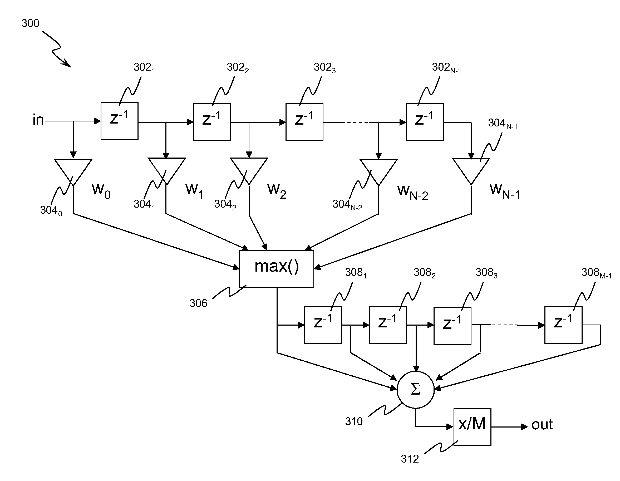
[0034]Preferred embodiments of the invention will now be described by way of example only. With reference to FIGS. 3 and 4 there will now be described a filter 300 according to a preferred embodiment. The filter 300 can be implemented to filter an input signal (“in”) to generate an output signal (“out”). The filter 300 comprises a first delay line which includes a plurality (N−1) of delay elements 3021 to 302N-1. The filter also comprises a plurality (N) of weighting elements 3040 to 304N-1 and a selection block 306. The filter 300 also comprises a supplementary filter which includes a second delay line having a plurality (M−1) of delay elements 3081 to 308M-1, a summation block 310 and a dividing block 312. A plurality (N) of taps are arranged to provide the output from each of the delay elements 302 in the first delay line to a respective one of the weighting elements 304. The outputs of each of the weighting elements 304 are coupled to the selection block 306. An output of the se...


PUM


Abstract

Method and filter for filtering a signal, in which the signal is applied to a delay line having a plurality of taps. Respective weighting coefficients of a windowing function are applied to outputs from the plurality of taps to thereby generate a plurality of weighted outputs. The method comprises repeatedly selecting, for output, whichever of the weighted outputs has the highest value.

Description

1. PRIORITY CLAIM[0001]This application claims priority to and the benefit of Great Britain Application No. 1105768.4 filed on Apr. 5, 2011.2. FIELD OF THE INVENTION[0002]The present invention relates to a filter, particularly but not exclusively for use in crest factor reduction.3. RELATED ART[0003]When a transmit signal is to be transmitted from a transmitter in a wireless network then the signal is amplified by a power amplifier. If the power of an input signal to the power amplifier is below a maximum power level, then the power amplifier operates in a linear manner where an increase in input power is matched by a proportional increase in the power of the output signal from the power amplifier, (i.e. the power amplifier operates in a linear region). However, if the power of the input signal exceeds the maximum power level, then the power amplifier operates in a nonlinear manner such that an increase in the power of the input signal is not matched by a proportional increase in th...

Claims


Application Information

Patent Timeline
Patent Type & Authority Applications(United States)
IPC IPC(8): H04B1/04
CPCH04L27/2624H03H17/0263H04B1/707H04L27/2623
Inventor SMART, CHRISTOPHER BRIAN
Owner INTEL CORP
Features
  • R&D
  • Intellectual Property
  • Life Sciences
  • Materials
  • Tech Scout
  • Unparalleled Data Quality
  • Higher Quality Content
  • 60% Fewer Hallucinations
Learn More