Cutting tool holder, cutting tool, and method of manufacturing machined product using the same

a technology of cutting tool and insert, which is applied in the direction of cutting inserts, manufacturing tools, shaping cutters, etc., can solve the problems of insufficient fixing of inserts and following risks, and achieve the effects of improving the fixation reliability of inserts, reducing chatter vibration, and improving fixation strength

Active Publication Date: 2012-10-18
KYOCERA CORP
View PDF14 Cites 5 Cited by
  • Summary
  • Abstract
  • Description
  • Claims
  • Application Information

AI Technical Summary

Benefits of technology

[0015]In the cutting tool holder and the cutting tool according to the one embodiment of the present invention, a force that the pressing member presses against the first fixing section acts more strongly on the first front end region than on the first rear end region of the first fixing section. Therefore, the pressing force of the pressing member can be effectively used as a force for fixing the insert, thereby improving fixation reliability of the insert.
[0016]In the cutting tool holder and the cutting tool according to the another embodiment of the present invention, the central axis of the through hole is eccentric to the holder front end region of the holder body with respect to the central axis of the hole portion, or the pressed surface pressed by the fixing section in the head member is inclined toward the head rear end region from the first side surface to the second side surface. Therefore, when the holder body and the head member are fixed together by the fixing member, the head member receives a force that moves to the head rear end region relative to the holder body, and the head rear end region of the head member is strongly contacted with the end portion of the wide part of the holder body close to the holder front end region, thereby improving fixation strength between the two. It is therefore capable of reducing chatter vibration between the head member and the holder body due to thrust force caused during cutting processing. This achieves an improvement of machining accuracy with respect to the workpiece. Particularly, an excellent effect can be produced under high feed conditions in which the thrust force becomes large.

Problems solved by technology

However, when the cutting processing is carried out using the foregoing cutting tool, a pressing force by the screw is insufficient, and hence there is a risk that the insert cannot sufficiently be fixed thereto.
However, according to this cutting tool, there has been the following risk.

Method used


Image

  • Cutting tool holder, cutting tool, and method of manufacturing machined product using the same
  • Cutting tool holder, cutting tool, and method of manufacturing machined product using the same
  • Cutting tool holder, cutting tool, and method of manufacturing machined product using the same

Examples


first embodiment

[0031]A first embodiment of a cutting tool holder and a cutting tool of the present invention is described in detail below with reference to FIGS. 1 and 2.

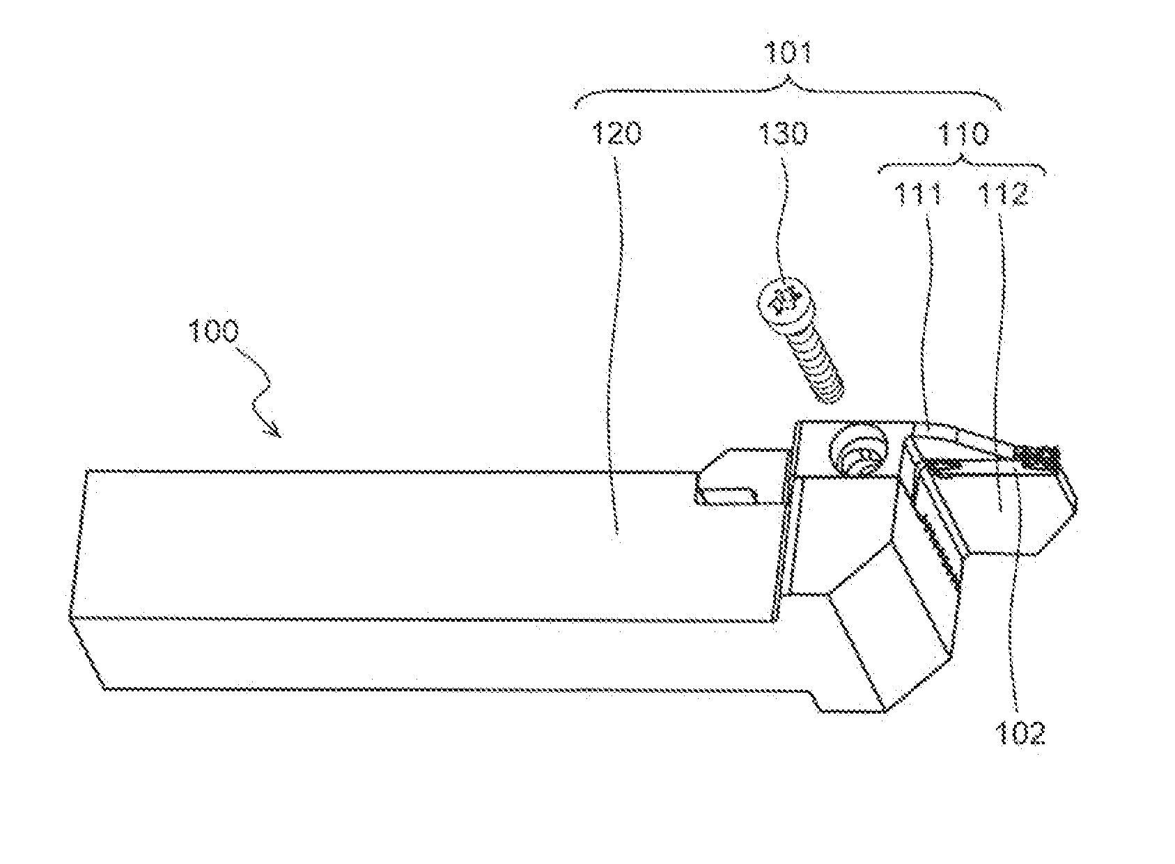
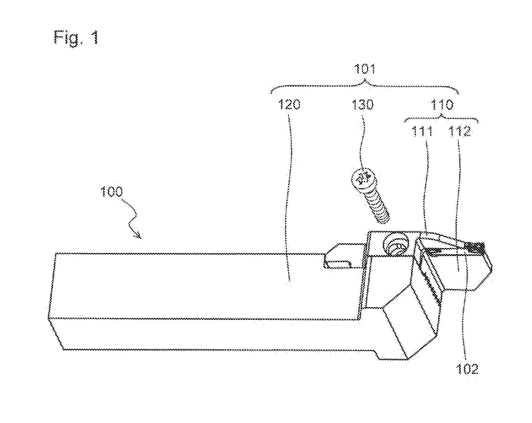
[0032]As shown in FIGS. 1 and 2, the cutting tool 100 of the present embodiment generally includes a holder 101 and an insert 102. The holder 101 includes a head member 110 having a first fixing section 111 (upper jaw) and a second fixing section 112 (lower jaw), a holder body 120, and a pressing member 130. The cutting tool 100 of the present embodiment is a so-called indexable tool in which the insert 102 is detachably attached to the holder 101. Individual components are described in due order below.

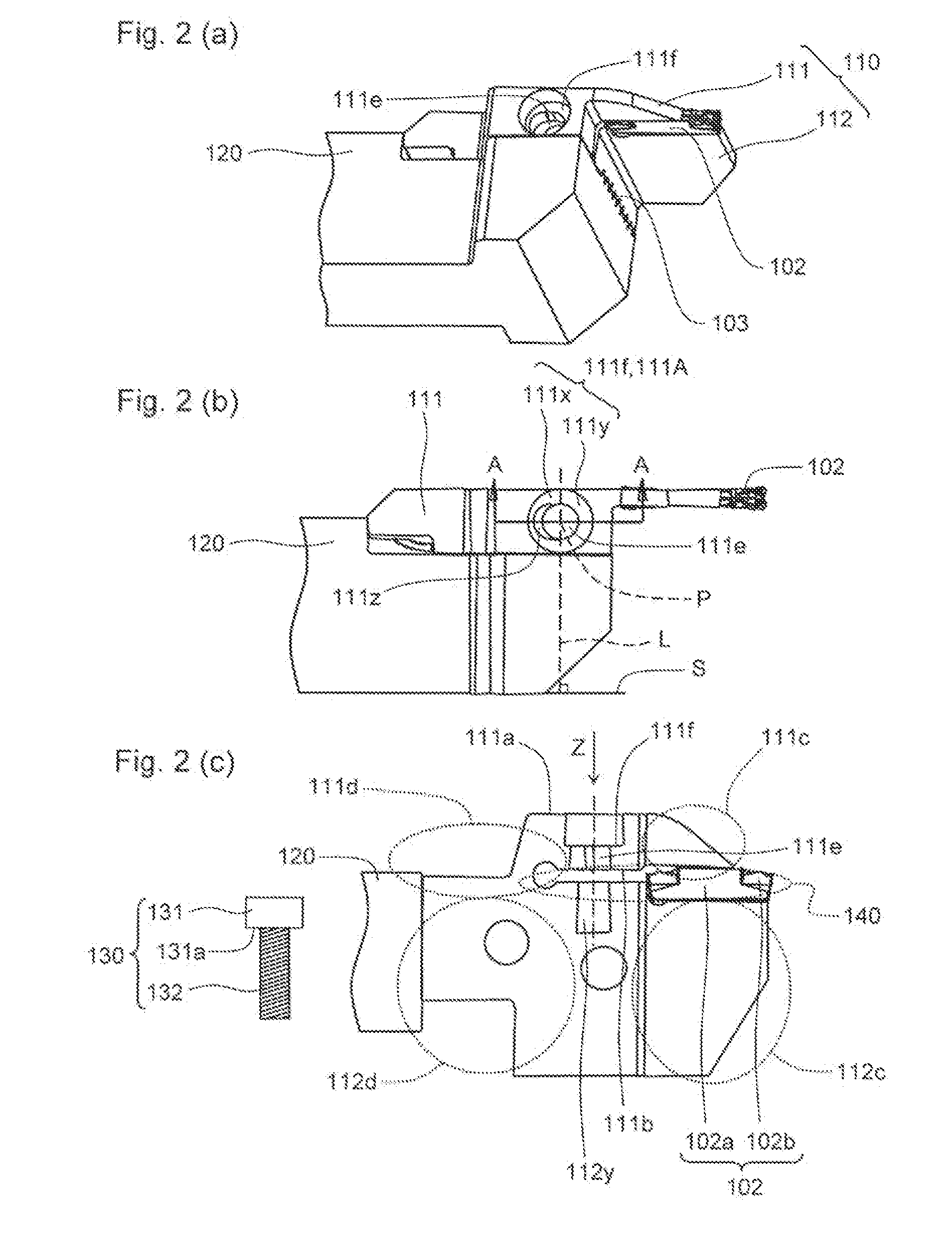
[0033]The head member 110 includes the first fixing section 111 and the second fixing section 112, and has the function of fixedly holding the insert 102 between the first fixing section 111 and the second fixing section 112. Preferably, the head member 110 has a shape that allows the head member to follow the insert 102 and enter t...

second embodiment

Modification of Second Embodiment

[0065]A modification of the foregoing second embodiment is described in details below with reference to FIGS. 4 and 5. In FIGS. 4 and 5, the same components as the foregoing FIG. 3 are identified by the same reference numerals, and descriptions thereof are omitted here.

[0066]In the cutting tool 200 according to the foregoing second embodiment, the first contact portion 211x and the second contact portion 211y of the contact part 211f of the first fixing section 211 exist on the same surface (flat surface). On the other hand, in a cutting tool 200′ of the present embodiment shown in FIGS. 4 and 5, a first contact portion 211x′ and a second contact portion 211y′ are configured as follows.

[0067]That is, in the present embodiment, the second contact portion 211y′ and a region 211g of the first contact portion 211x′ close to the first front end region 211c exist on the same surface (flat surface), and a region 211h close to the first rear end region 211d ...

third embodiment

[0070]A third embodiment of the holder and the cutting tool according to the present invention is described in details below with reference to FIG. 6.

[0071]As shown in FIG. 6, a cutting tool 300 of the present embodiment generally includes a holder 301 and an unshown insert. The holder 301 includes a first fixing section 311, a second fixing section 312, and a pressing member 330. That is, the cutting tool 300 of the present embodiment has a configuration in which the head member 110 or 210 and the holder body 120 or 220 in the cutting tool 100 of the first embodiment or the cutting tool 200 of the second embodiment are integrated with each other. Individual components are described in due order below.

[0072]As shown in FIG. 6(c), in the first fixing section 311 and the second fixing section 312, a first rear end region 311d of the first fixing section 311 and a second rear end region 312d are integrated with each other so that a fixing space 340 extending from a second rear end regi...


PUM

PropertyMeasurementUnit
areaaaaaaaaaaa
widthaaaaaaaaaa
thrustaaaaaaaaaa

Abstract

A cutting tool holder includes a pressing member with a pressing part and an inserting part, a holder body, a head member including a first fixing section which is divided into a first front end region and a first rear end region, and has a first fixing hole for inserting the inserting part of the pressing member and a contact part pressed by the pressing part of the pressing member, at a portion of a first surface close to the first front end region in reference to the first rear end region; and a second fixing section divided into a second front end region and a second rear end region in which the first rear end region of the first fixing section and the second rear end region are connected to each other so that a fixing space extending from the second rear end region to the second front end region is located between the second fixing section and a second surface different from the first surface in the first fixing section. The contact part includes a first contact portion located close to the first rear end region and a second contact portion located close to the first front end region in reference to a midpoint of the first fixing hole. An area of the second contact portion is larger than an area of the first contact portion. A cutting tool including the cutting tool holder, and a method of manufacturing a machined product using the cutting tool are also provided.

Description

TECHNICAL FIELD[0001]The present invention relates to a cutting tool holder, a cutting tool, and a method of manufacturing a machined product using the same, which are used for cutting processing of metal components or the like.BACKGROUND ART[0002]Cutting tools used for grooving, cutoff process, or the like of metal components or the like have conventionally been known. For example, as shown in FIG. 1 of Japanese Unexamined Patent Application Publication No. 2001-001204, the cutting tool includes a configuration for fixing a cutting insert (hereinafter referred to as an “insert” in some cases) to between a lower jaw and an upper jaw of a cutting tool holder (hereinafter referred to as a “holder” in some cases) by inserting a screw from an upper part of the holder to a vertical lower side, and by pressing down the upper jaw of the holder.[0003]However, when the cutting processing is carried out using the foregoing cutting tool, a pressing force by the screw is insufficient, and hence...

Claims


Application Information

Patent Timeline
Patent Type & Authority Applications(United States)
IPC IPC(8): B23B27/16B23B1/00
CPCB23B29/043B23B29/046B23B2205/02Y10T82/10B23B2260/132Y10T407/2282B23B2260/124
Inventor UNO, TETSUYA
Owner KYOCERA CORP
Why Eureka
Try Eureka