Compressor inter-stage temperature control

a compressor and temperature control technology, applied in mechanical equipment, refrigeration components, light and heating equipment, etc., can solve the problems of condensation of vapor and formation of recycle loops

Inactive Publication Date: 2012-10-18
HEATH RODNEY T +2
View PDF12 Cites 49 Cited by
  • Summary
  • Abstract
  • Description
  • Claims
  • Application Information

AI Technical Summary

Benefits of technology

[0016]The accompanying drawing, which is incorporated into and forms a part of the specification, illustrates one or more embodiments of the present invention and, together with the description, serves to explain the principles of the invention. The dra

Problems solved by technology

One of the major problems encountered with known vapor recovery systems is condensation of the vapors in the air-cooled compressor, which compressor is used to raise the pressure of th

Method used


Image

  • Compressor inter-stage temperature control
  • Compressor inter-stage temperature control

Examples


Embodiment Construction

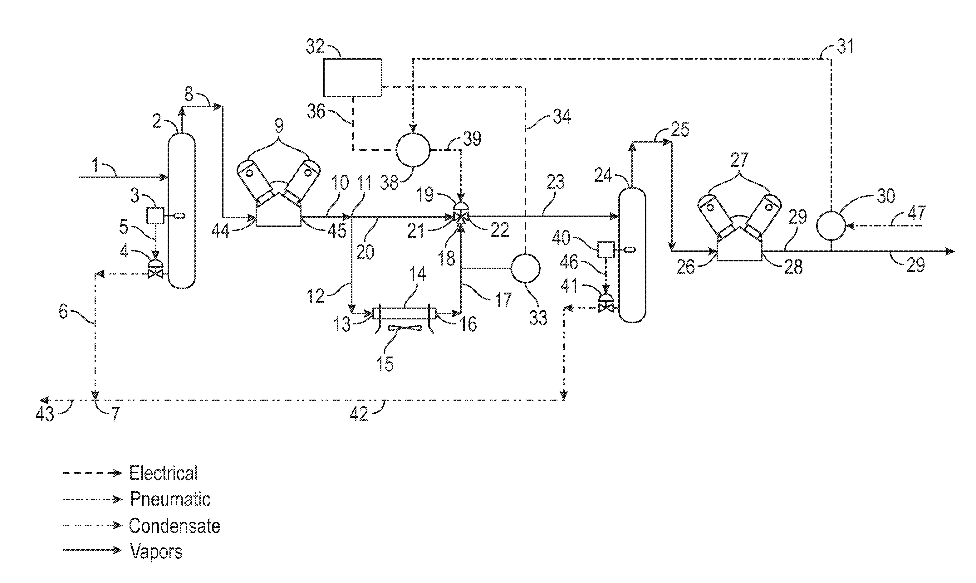
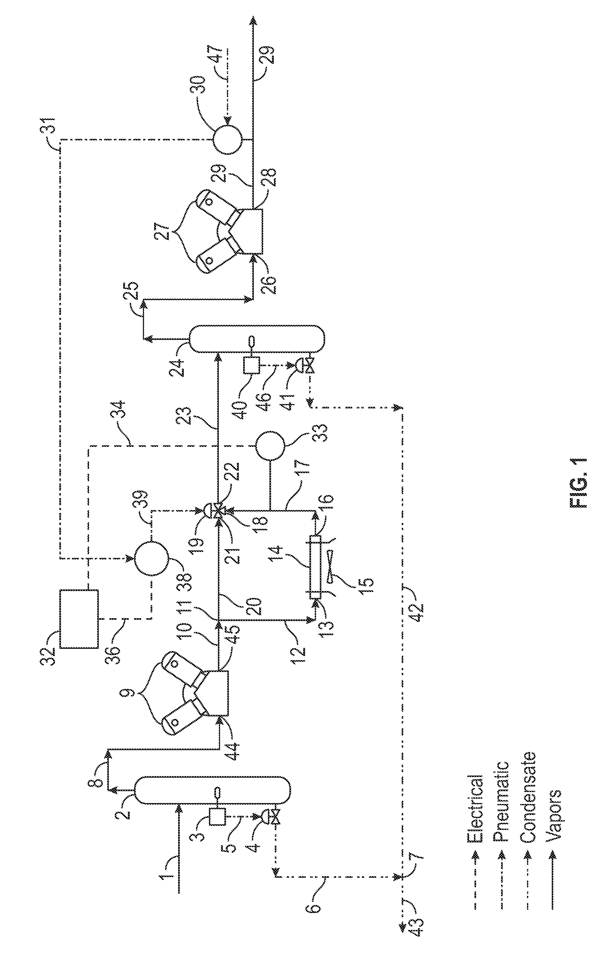
[0008]An embodiment of the present invention relates to a method for regulating temperature of a gas between stages of compression which includes providing a control valve between stages of compression; providing an air-cooled heat exchanger; monitoring the temperature of the gas in at least one location; and manipulating the control valve such that at least a portion of compressed gas from a first stage of compression can be selectively caused to flow through the air-cooled heat exchanger before being introduced into a second stage of compression. The at least one location can be downstream of an outlet of the second stage of compression. The at least one location can be between an outlet of the air-cooled heat exchanger and an inlet of the control valve. Manipulating the control valve can include modulating the control valve.

[0009]In one embodiment, the control valve can include a first inlet which is coupled to an outlet of the first stage of compression, the control valve can in...


PUM


Abstract

A method, system and apparatus for providing temperature control of compressed gases between stages of a multiple-stage compressor, by selectively manipulating a valve which can cause at least a portion of the compressed gases to flow through an air-cooled heat exchanger.

Description

CROSS-REFERENCE TO RELATED APPLICATIONS[0001]This application claims priority to and the benefit of the filing of U.S. Provisional Patent Application Ser. No. 61 / 476,099, entitled “Compressor Inter-Stage Temperature Control”, filed on Apr. 15, 2011, and the specification thereof is incorporated herein by reference.BACKGROUND OF THE INVENTION[0002]1. Field of the Invention (Technical Field)[0003]Embodiments of the present invention relate to a method, system, and apparatus for providing inter-stage temperature control of a compressor, particularly at least partially via the use of an air cooler.[0004]2. Description of Related Art[0005]One of the major problems encountered with known vapor recovery systems is condensation of the vapors in the air-cooled compressor, which compressor is used to raise the pressure of the recovered vapors to the pressure of the sales line. In known systems, some of the recovered vapors are at liquid phase at the typical sales line pressures, but change to...

Claims


Application Information

Patent Timeline
IPC IPC(8): F28F27/00
CPCF25B1/10F25B41/04F25B2600/2507F25B2400/072F25B49/022F25B41/20
Inventor HEATH, RODNEY T.HEATH, GARYHEATH, FORREST D.
Owner HEATH RODNEY T
Why Eureka
Try Eureka