Solid state light source based lighting device and lighting system

Inactive Publication Date: 2012-10-18
PANASONIC CORP
View PDF2 Cites 37 Cited by
  • Summary
  • Abstract
  • Description
  • Claims
  • Application Information

AI Technical Summary

Benefits of technology

[0019]According to one aspect, the first switching controller is provided to change an on-time of the switching element and the second switching controller is provided to perform an energizing/de-energizing control for the switching element, wherein the energizing period of the second

Problems solved by technology

However, operation becomes unstable before and after switching

Method used


Image

  • Solid state light source based lighting device and lighting system
  • Solid state light source based lighting device and lighting system
  • Solid state light source based lighting device and lighting system

Examples


Embodiment Construction

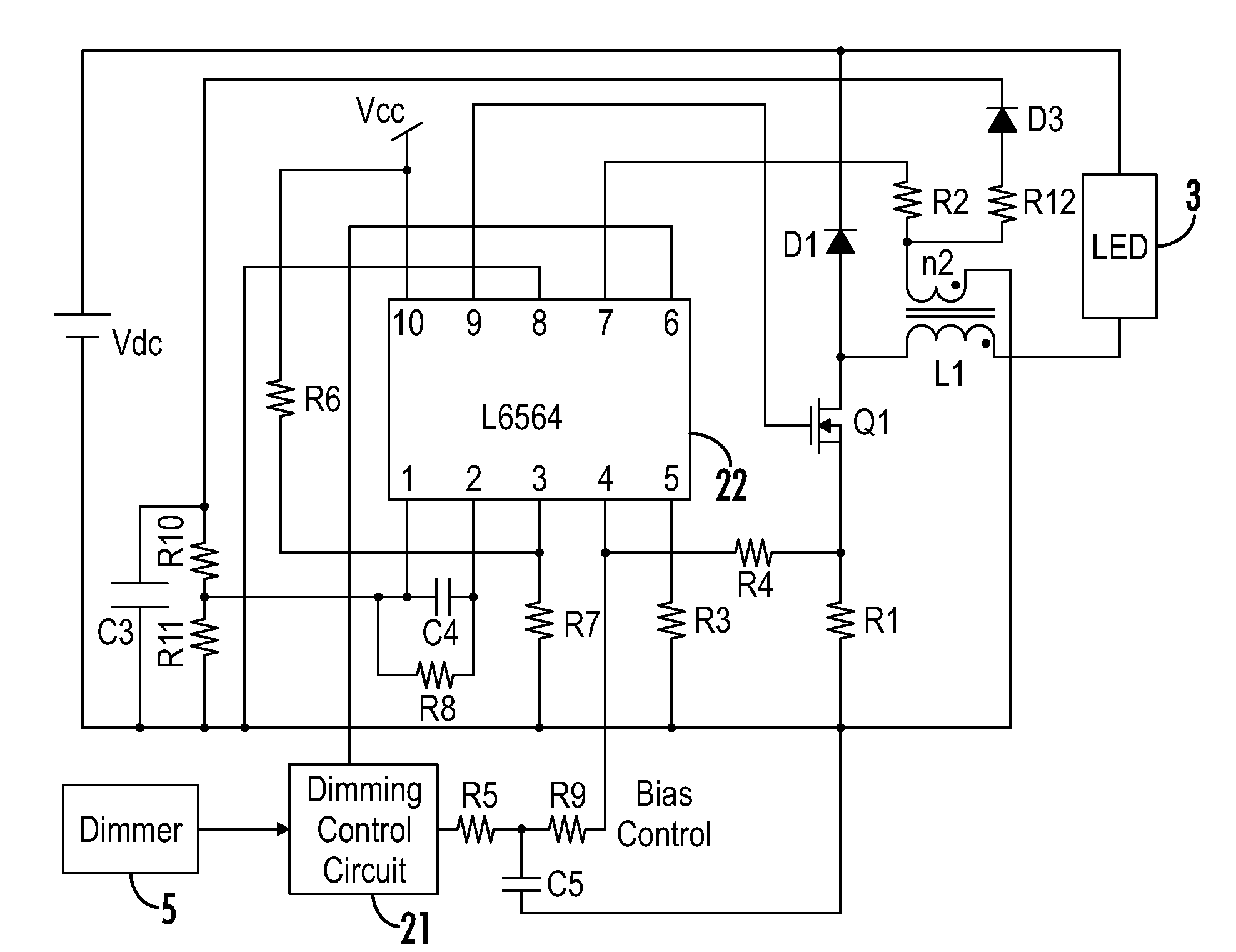
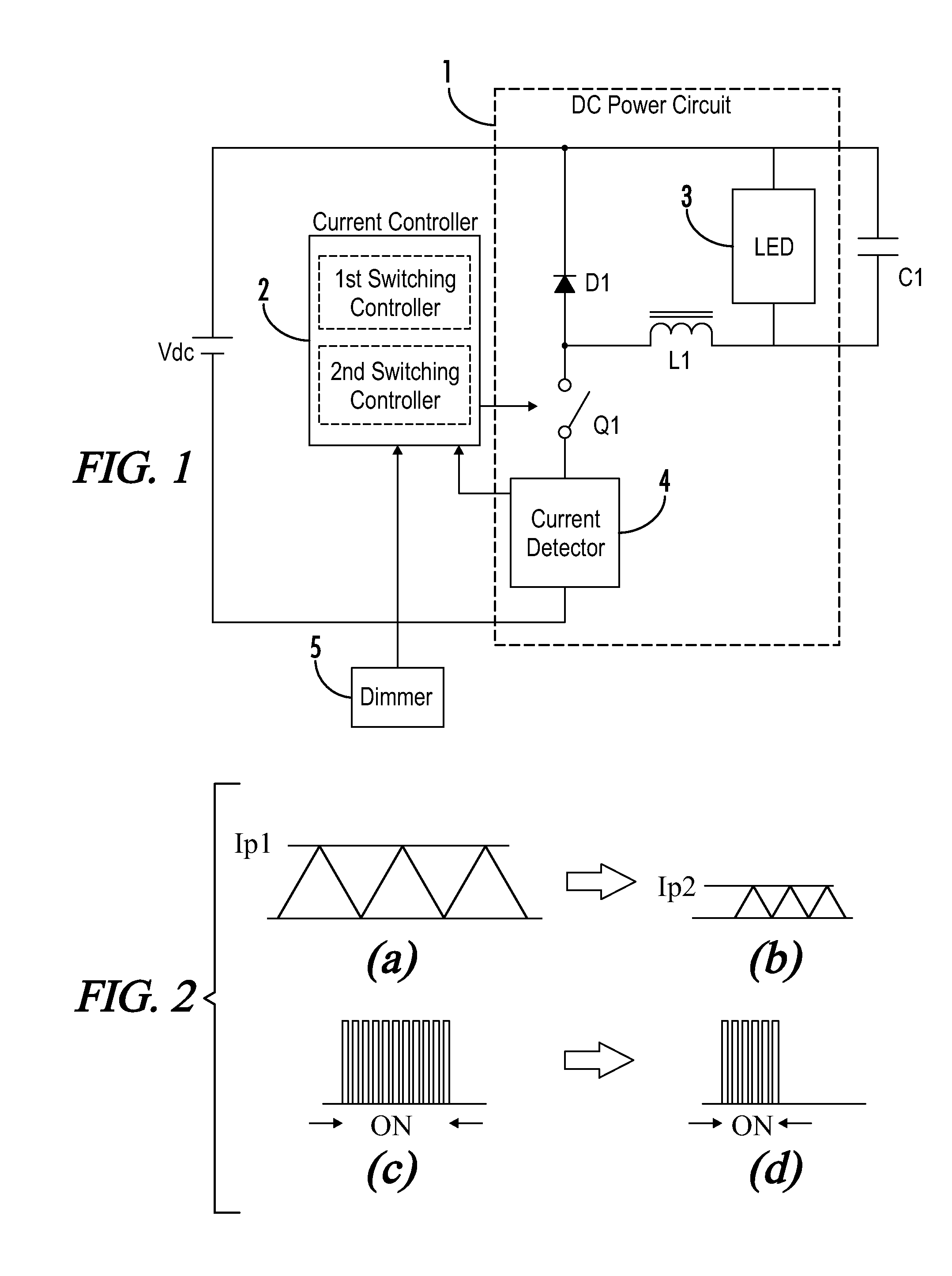
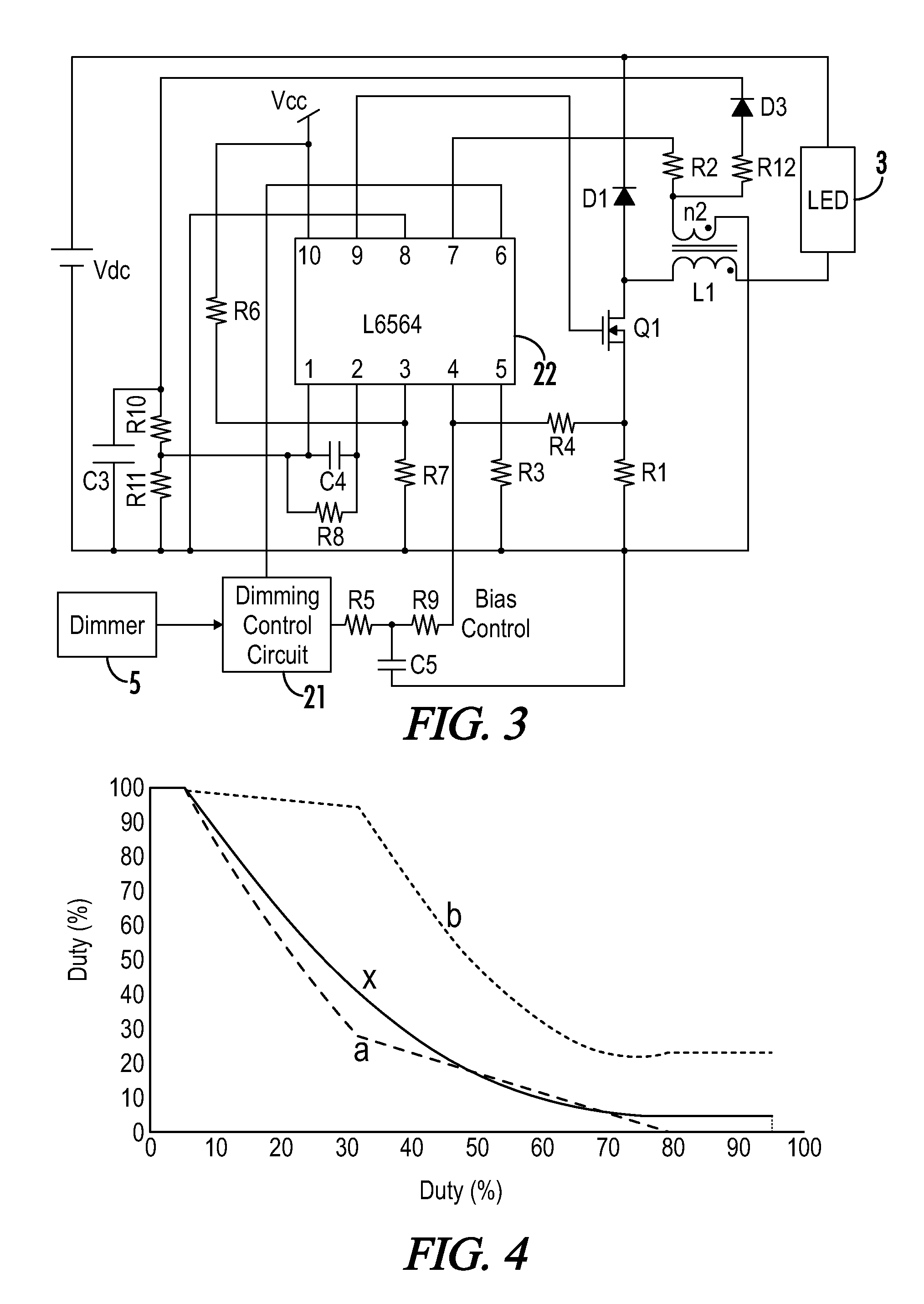
[0030]FIG. 1 is a circuit diagram showing one embodiment of a lighting device according to the present invention. A DC power circuit 1 is connected to an input DC power source Vdc. In this embodiment, the DC power circuit 1 is a switching power circuit. Power supplied by the input DC power source Vdc is converted by using a switching element Q1 so as to supply a DC current to the solid state light source 3 such as an LED (or organic EL element). In this embodiment, a step-down chopper circuit (or back converter) is used.

[0031]The step-down chopper circuit has a well-known configuration in which, between a positive pole and a negative pole of the input DC power source Vdc, a series circuit including the solid state light source 3, an inductor L1, the switching element Q1 and a current detector 4 is connected. A regenerative diode D1 is connected in parallel with the series-connected solid state light source 3 and the inductor L1 so as to form a closed circuit.

[0032]The step-down chop...


PUM


Abstract

A lighting device is capable of realizing a stable dimming control in a wide range of light output. The lighting device includes a DC power circuit for providing power to a switching element of the lighting device. A current controller switches the switching element to enable a current to flow from the DC power circuit through a solid state light source and maintain the current from the DC power circuit through the solid state light source current controller at a predetermined current. The current controller includes a first switching controller operable to change a width of an on-pulse provided to the switching element and a second switching controller operable to determine a burst-on time during which the on-pulses determined by the first switching controller are provided to the switching element. The burst-on time is longer than an on-pulse period of the first switching controller.

Description

[0001]A portion of the disclosure of this patent document contains material that is subject to copyright protection. The copyright owner has no objection to the reproduction of the patent document or the patent disclosure, as it appears in the U.S. Patent and Trademark Office patent file or records, but otherwise reserves all copyright rights whatsoever.CROSS-REFERENCES TO RELATED APPLICATIONS[0002]This application claims benefit of the following patent application(s) which is hereby incorporated by reference: Japanese Patent Application No. 2011-065091, filed Mar. 23, 2011.STATEMENT REGARDING FEDERALLY SPONSORED RESEARCH OR DEVELOPMENT[0003]Not ApplicableREFERENCE TO SEQUENCE LISTING OR COMPUTER PROGRAM LISTING APPENDIX[0004]Not ApplicableBACKGROUND OF THE INVENTION[0005]The present invention relates to a solid state light source lighting device for lighting a solid state light source such as a light-emitting diode (LED), as well as a lighting system using the same.[0006]Japanese P...

Claims


Application Information

Patent Timeline
IPC IPC(8): H05B37/02H05B44/00
CPCH05B33/0818Y02B20/347H05B33/0851H05B45/10Y02B20/30H05B45/38H05B45/3725H05B45/375H05B45/385
Inventor WATANABE, KOJIMIZUKAWA, HIROMITSUUKITA, NOBUONISHIMOTO, KAZUHIRO
Owner PANASONIC CORP
Why Eureka
Try Eureka