Radio-frequency test probes with integrated matching circuitry

a technology of matching circuitry and radio frequency, applied in the field of testing, can solve the problems of insufficient space for the placement of the switch connector on the printed circuit board, see a 50 ohm impedance,

Active Publication Date: 2012-10-18
APPLE INC
View PDF3 Cites 32 Cited by
  • Summary
  • Abstract
  • Description
  • Claims
  • Application Information

AI Technical Summary

Benefits of technology

[0011]In another suitable test arrangement, a coaxial test probe may be mated with the first antenna connector during transceiver testing/calibration. In this embodiment, jumpers and test pads need not be present on the printed circuit board. The coaxial test probe may include integrated matching circuitry. For example, the coaxial test probe may include an inner signal conductor and a surrounding shielding ground conductor. The integrated matching circuitry may include passive surface mount components such as capacitors, inductors, and resistors soldered in p...

Problems solved by technology

As device size continues to decrease, there may be insufficient space for the placement of the switch connector on the printed circuit board.
If, however, the antenna resonating element is decoupled from the antenna connector and the a...

Method used


Image

  • Radio-frequency test probes with integrated matching circuitry
  • Radio-frequency test probes with integrated matching circuitry
  • Radio-frequency test probes with integrated matching circuitry

Examples


Embodiment Construction

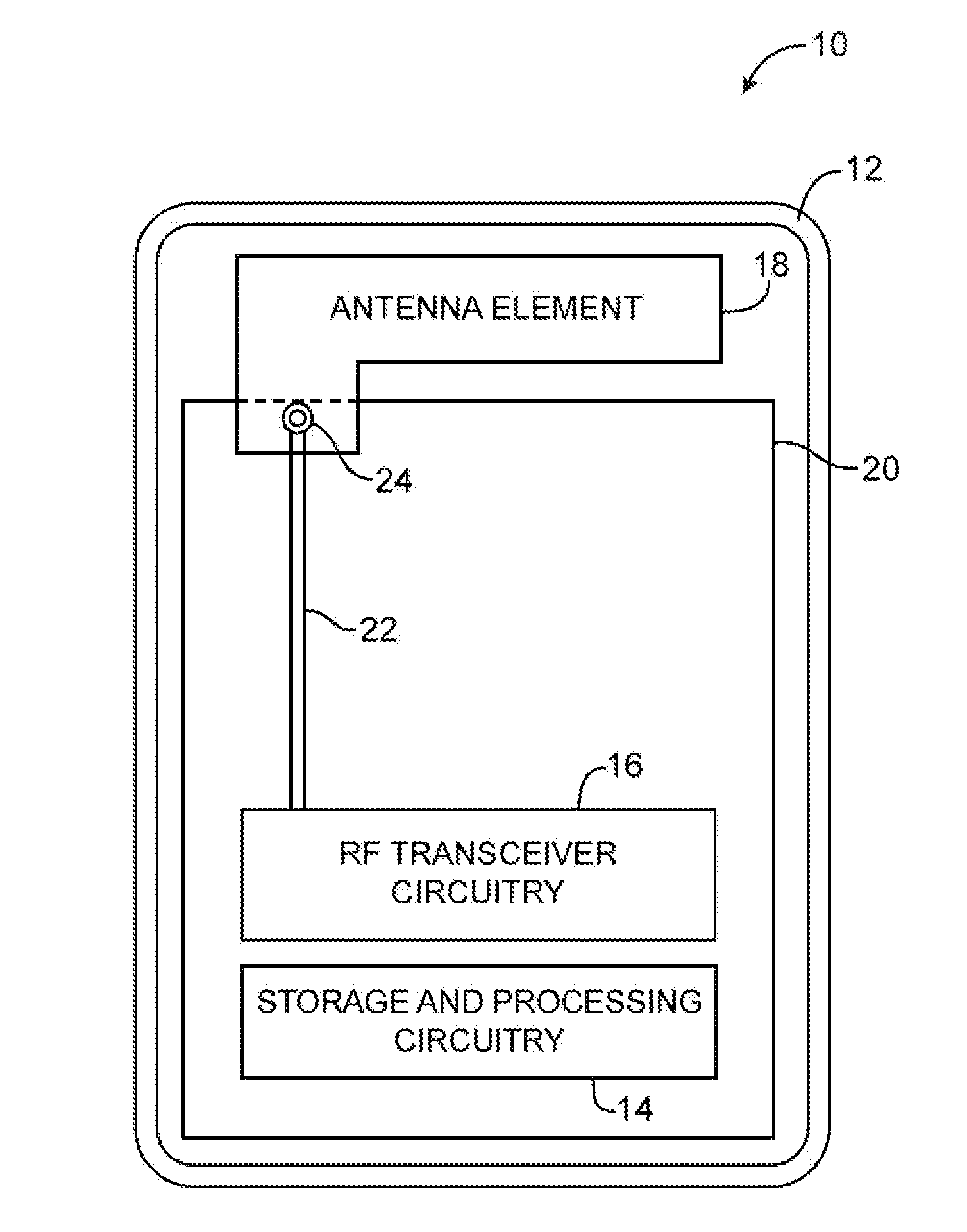
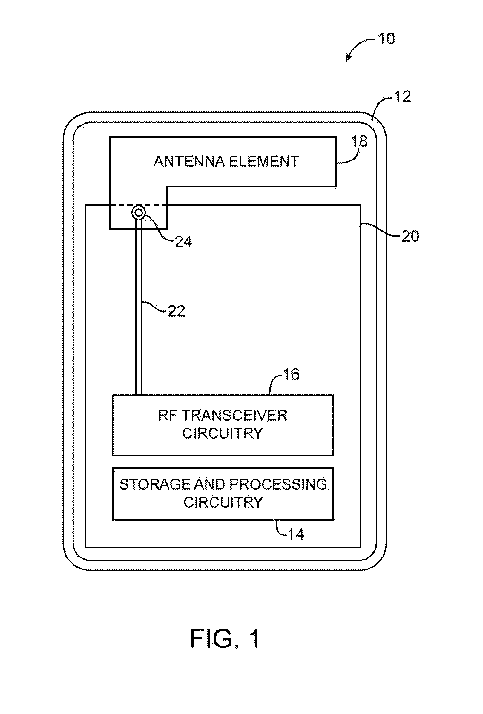
[0021]Wireless electronic devices include antenna and transceiver circuitry that support wireless communications. Examples of wireless electronic devices include desktop computers, computer monitors, computer monitors containing embedded computers, wireless computer cards, wireless adapters, televisions, set-top boxes, gaming consoles, routers, and other electronic equipment. Examples of portable wireless electronic devices include laptop computers, tablet computers, handheld computers, cellular telephones, media players, and small devices such as wrist-watch devices, pendant devices, headphone and earpiece devices, and other miniature devices.

[0022]Devices such as these are often provided with wireless communications capabilities. For example, electronic devices may use long-range wireless communications circuitry such as cellular telephone circuitry to communicate using cellular telephone bands at 850 MHz, 900 MHz, 1800 MHz, and 1900 MHz (e.g., the main Global System for Mobile Co...


PUM


Abstract

Wireless electronic devices include wireless communications circuitry such as transceiver circuitry coupled to an antenna resonating element. The transceiver circuitry and the antenna element may be formed on first and second substrates, respectively. In compact wireless devices, transceiver and antenna matching circuits may be formed on the first substrate. During production testing, a radio-frequency test probe with integrated matching circuitry may be used to mate with a corresponding contact point on the first substrate. The integrated matching circuitry may include resistors, capacitors, and inductors soldered in desired series-parallel configurations within the test probe. When the test probe is mated to the contact point on the first substrate, a test unit connected to the test probe may be used to perform radio-frequency measurements to determine whether the transceiver circuitry satisfies design criteria.

Description

BACKGROUND[0001]This relates to testing and, more particularly, to testing of electronic device structures.[0002]Electronic devices such as computers, cellular telephones, music players, and other electronic equipment are often provided with wireless communications circuitry.[0003]In a typical configuration, the wireless communications circuitry includes a radio-frequency transceiver, a transceiver matching circuit, an antenna matching circuit, a switch connector, and an antenna connector each of which is mounted on a printed circuit board. The wireless communications circuitry also includes an antenna. The antenna includes an antenna resonating element that is coupled to the transceiver through the antenna connector or other coupling mechanism (i.e., via a screw or a spring).[0004]The switch connector is connected between the transceiver and the antenna resonating element. During normal device operation, the switch connector serves to electrically connect the transceiver to the ant...

Claims


Application Information

Patent Timeline
IPC IPC(8): G01R27/04
CPCG01R1/06772H04B17/20G01R31/2822
Inventor NICKEL, JOSHUA G.SCHLUB, ROBERT W.
Owner APPLE INC
Why Eureka
Try Eureka