
Beam forming antenna

a beam-forming antenna and beam-forming technology, applied in the direction of antennas, elongated active element feeds, electrical devices, etc., can solve the problems of poor long-distance performance, significant signal loss, poor reception

Inactive Publication Date: 2012-10-18
WALLNER GEORGE
View PDF5 Cites 6 Cited by
  • Summary
  • Abstract
  • Description
  • Claims
  • Application Information

AI Technical Summary

Benefits of technology

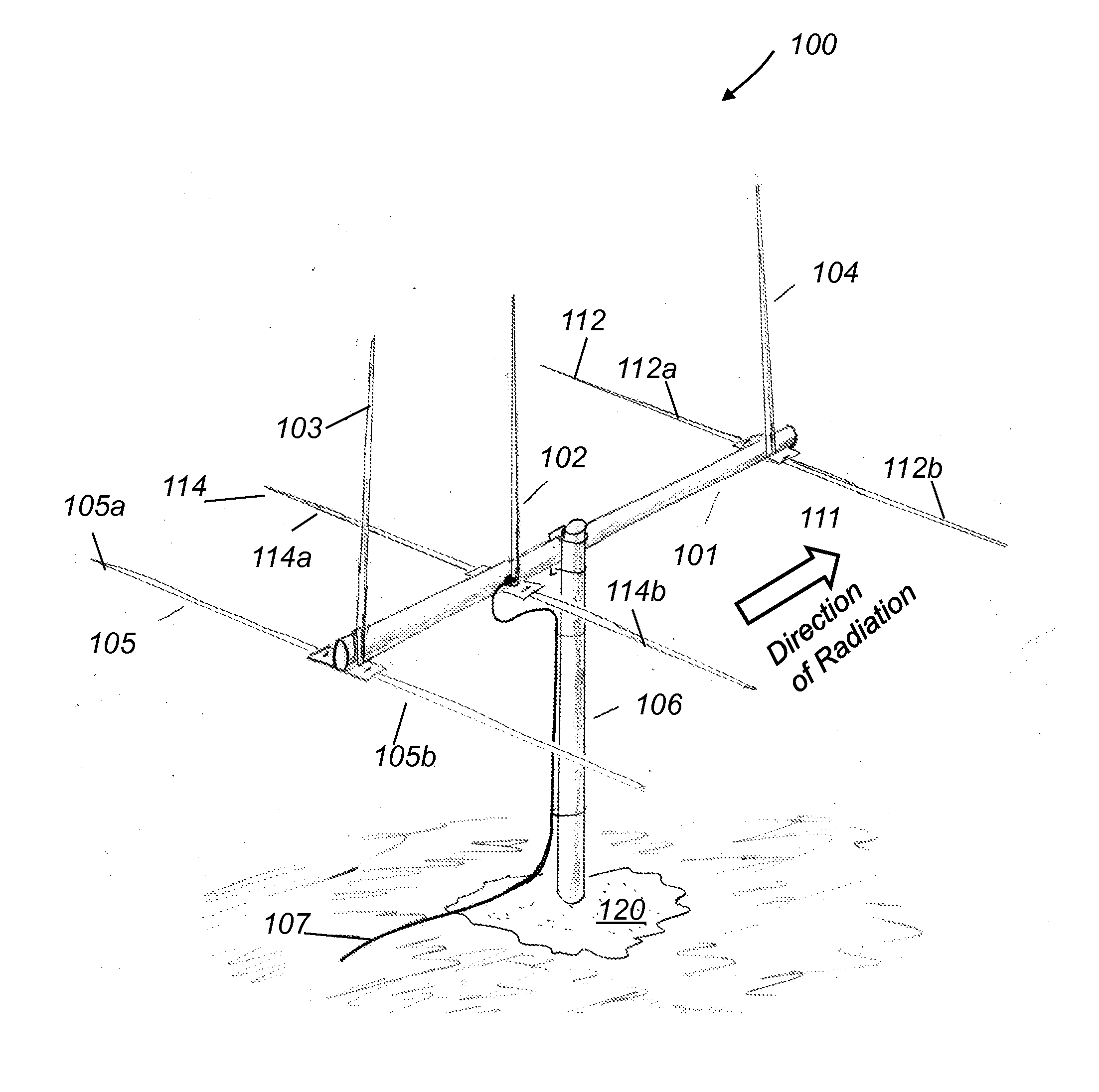
[0009]This invention describes a beam forming HF antenna that satisfies the need for a high performance gain antenna that provides low angles of radiation when installed at 0.1 to 0.2 wavelength above ground. The antenna eliminates the need for a tower in the HF service.
[0010]In general, one aspect of the invention provides a high frequency (HF) beam antenna including a set of radiating vertical monopole elements and a set of horizontal dipole elements. The horizontal dipole elements are parasitically coupled to corresponding radiating vertical monopole elements and are configured to counterpoise radiation from the radiating vertical monopole elements and to effectively isolate the vertical monopole elements from the underlying ground.
[0013]Among the advantages of this invention may be one or more of the following. The rotatable vertically polarized beam forming antenna achieves low radiation angles from moderate heights (0.1 to 0.2 wavelength above ground) and does not suffer from excessive ground losses. Because this antenna does not require a tower, it can be installed in neighborhoods with restrictions on tall structures.

Problems solved by technology

When mounted low above the ground, horizontally polarized antennas have high radiation angles resulting in poor long distance performance.
Multiple hops result in significant signal loss and thus poor reception.
Compromise heights of 0.5 to one wavelength result in compromised performance and significant ground losses.
At lower heights the horizontally polarized antenna is almost useless for long distance communications.
This requirement severely restricts their use in residential areas where either local ordinances or community covenants restrict the height and visibility of structures.
A large number of amateur radio operators, who live in neighborhoods with antenna restrictions, are not able install towers and therefore are seriously disadvantaged.
They are limited to low dipole or ground mounted vertically polarized antennas that have either no, or limited beam forming capabilities, and suffer from ground losses.
Vertically polarized beam forming antennas are usually phased vertical arrays that require extensive radial fields, and therefore they often suffer from high ground losses.
Their performance is strongly dependent on ground quality, and can be very poor when mounted over low conductivity ground.

Method used


Image

  • Beam forming antenna
  • Beam forming antenna
  • Beam forming antenna

Examples


Embodiment Construction

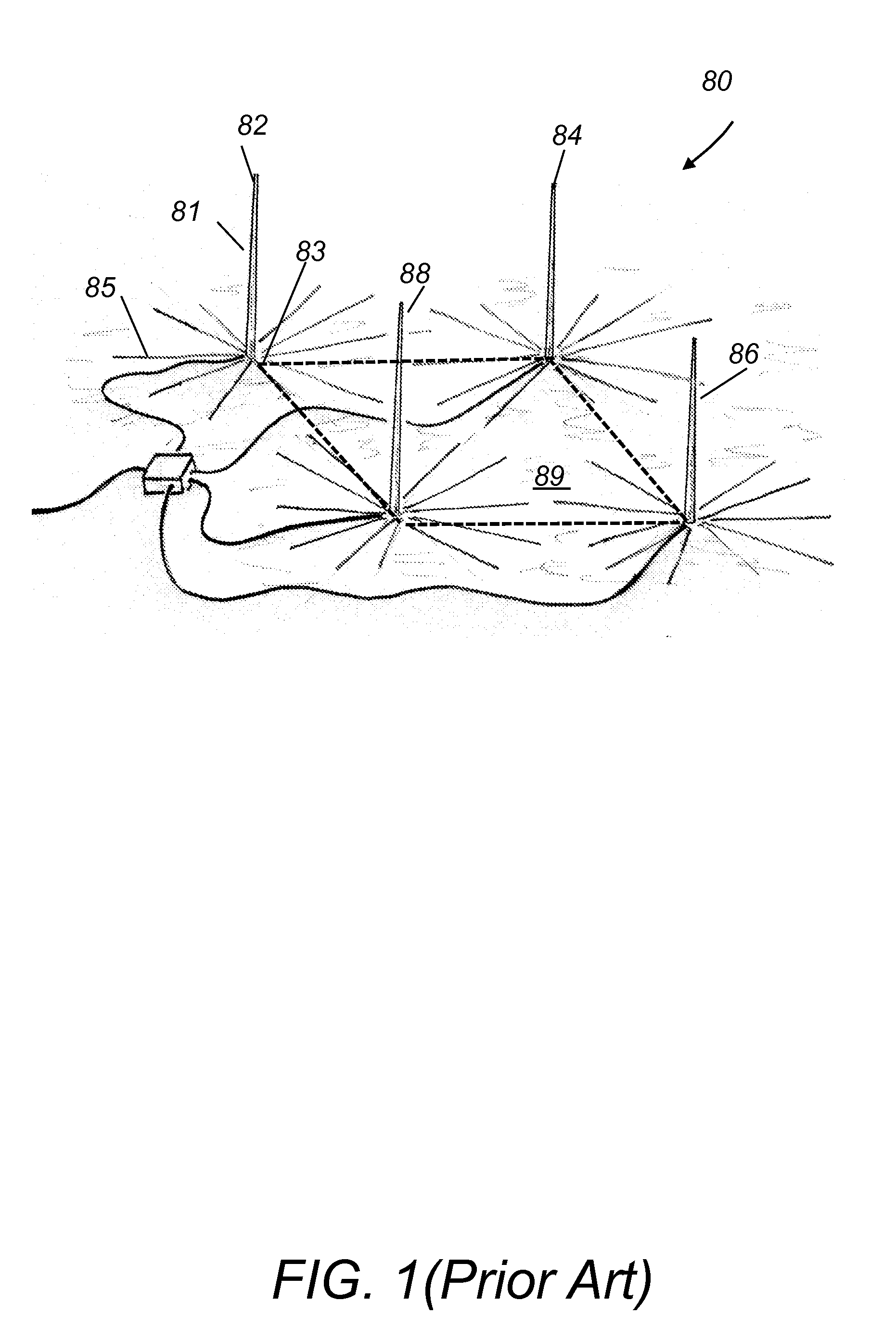
[0018]Beam forming antennas in the HF service are either vertically or horizontally polarized. Referring to FIG. 1, a vertically polarized phased array of vertical antennas 80, called Four Square, includes four vertical antennas 82, 84, 86 and 88 that are arranged in the corners of a square 89. Each vertical antenna has a vertical mast 81 and a plurality of horizontal wires (radials) 85 extending radially from its base 83. The number and length of radials 85 strongly affect performance. Radials 85 are either buried or laying on the ground. Low ground conductivity (common in suburban environments) must be compensated for by adding more and longer radials. Because of these requirements, vertical arrays are seldom used by space limited stations.

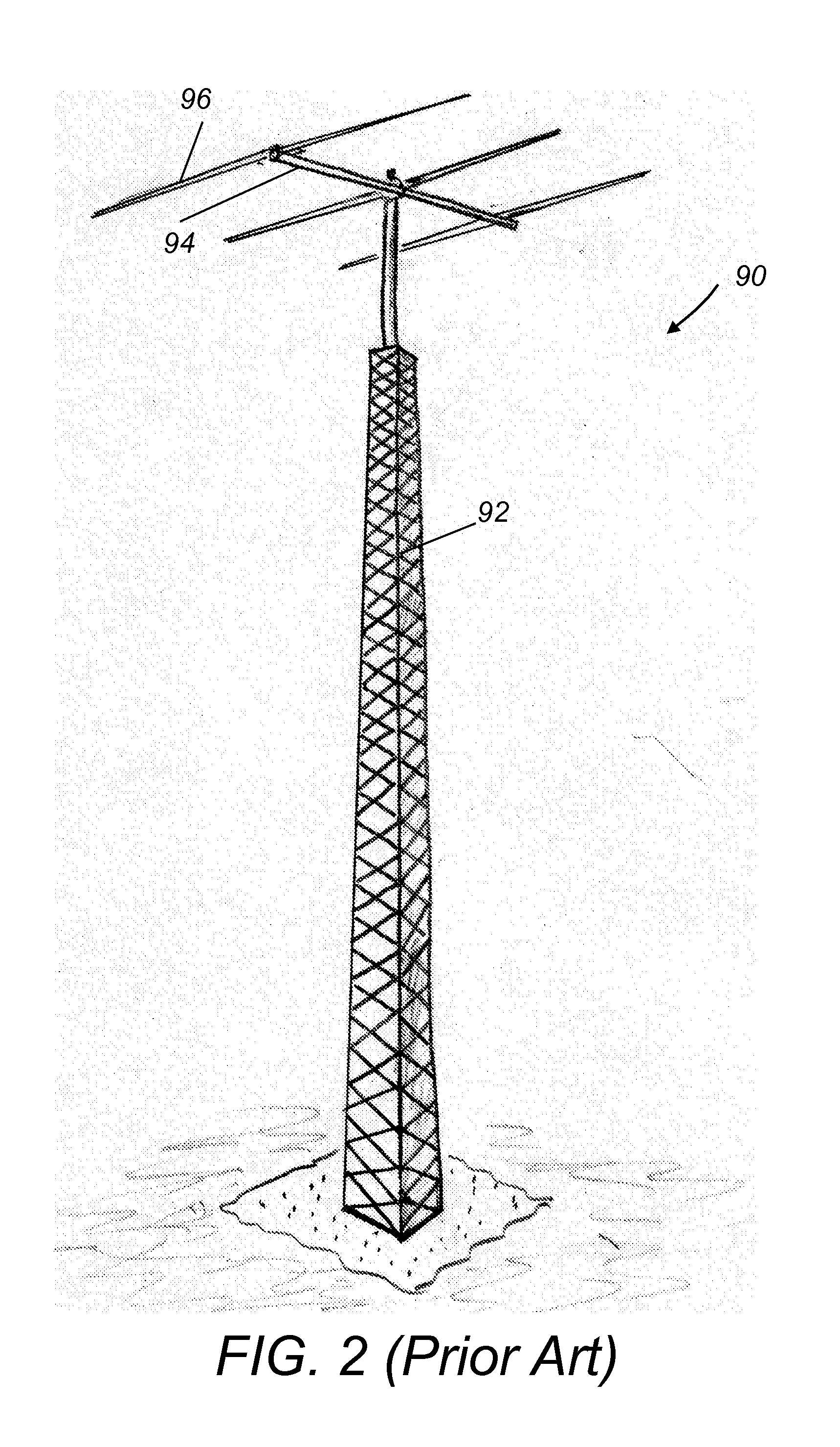
[0019]Referring to FIG. 2, horizontally polarized beam forming antennas 90, such as Yagi and Log-Periodic antennas, must be mounted one wave-length above the ground to achieve low angles (20 degrees or less) of radiation and to avoid significant...


PUM


Abstract

A high frequency (HF) beam antenna includes a set of radiating vertical monopole elements and a set of horizontal dipole elements. The horizontal dipole elements are parasitically coupled to corresponding radiating vertical monopole elements and are configured to counterpoise radiation from the radiating vertical monopole elements and to effectively isolate the vertical monopole elements from the underlying ground. The HF beam antenna has a high performance gain and low angles of radiation when installed at a height of 0.1 to 0.2 wavelength above ground. The HF beam antenna eliminates the need for a tower in the HF service range.

Description

CROSS REFERENCE TO RELATED CO-PENDING APPLICATIONS[0001]This application claims the benefit of U.S. provisional application Ser. No. 61 / 474,787 filed on Apr. 13, 2011 and entitled BEAM FORMING ANTENNA which is commonly assigned and the contents of which are expressly incorporated herein by reference.FIELD OF THE INVENTION[0002]The present invention relates to a high frequency (HF) beam forming antenna that satisfies the need for a high performance gain antenna.BACKGROUND OF THE INVENTION[0003]Beam forming high frequency (HF) (2 to 30 MHz) antennas, such as Yagi and Log-Periodic antennas, are usually horizontally polarized. When mounted low above the ground, horizontally polarized antennas have high radiation angles resulting in poor long distance performance.[0004]Long distance communications at HF frequencies rely on the ionosphere refracting signals back to earth. These refractions occur at heights of 200 to 300 kilometers. To reach long distances (2000 to 4000 km), signals must b...

Claims


Application Information

Patent Timeline
IPC IPC(8): H01Q19/10
CPCH01Q9/38H01Q21/061H01Q19/32
Inventor WALLNER, GEORGE
Owner WALLNER GEORGE
Learn More