Piezoelectric element drive circuit and fluid ejection device

a technology of piezoelectric elements and drive circuits, which is applied in the direction of printing, other printing apparatus, etc., can solve the problems of large storage capacity on the drive circuit side, difficult to increase (to raise the drive frequency of piezoelectric elements) the number, and become unachievable to eject fluid normally

Inactive Publication Date: 2012-10-18
SEIKO EPSON CORP
View PDF13 Cites 20 Cited by
  • Summary
  • Abstract
  • Description
  • Claims
  • Application Information

AI Technical Summary

Benefits of technology

[0017]As described above, the piezoelectric element drive circuit according to this aspect of the invention is capable of applying a number of types of drive signals to the piezoelectric element even if a large storage capacity is not installed. Therefore, it becomes possible to easily realize the fluid ejection device capable of ejecting the fluid in a plurality of manners.

Problems solved by technology

However, according to the technology thus proposed, since the plurality of types of drive signals needs to be stored previously, there is a problem that a large storage capacity is required on the drive circuit side.
Further, since the plurality of types of drive signals is output in series from the drive circuit, in the case of selecting a certain type of drive signal (e.g., the drive signal A), it is not achievable to select the target drive signal (the drive signal A) during the period in which other types of drive signals (e.g., the drive signals B, C) are output.
Therefore, there is another problem that it is difficult to increase (to raise the drive frequency of the piezoelectric element) the number of times of driving of the piezoelectric element per hour.
If the drive signal is applied to the piezoelectric element in the state in which such a pressure fluctuation (the flow of the fluid) remains, the pressure variation of the fluid chamber due to the expansion or contraction of the piezoelectric element is disturbed by the pressure fluctuation, and it becomes unachievable to eject the fluid normally.

Method used


Image

  • Piezoelectric element drive circuit and fluid ejection device
  • Piezoelectric element drive circuit and fluid ejection device
  • Piezoelectric element drive circuit and fluid ejection device

Examples


first modified example

D-1. First Modified Example

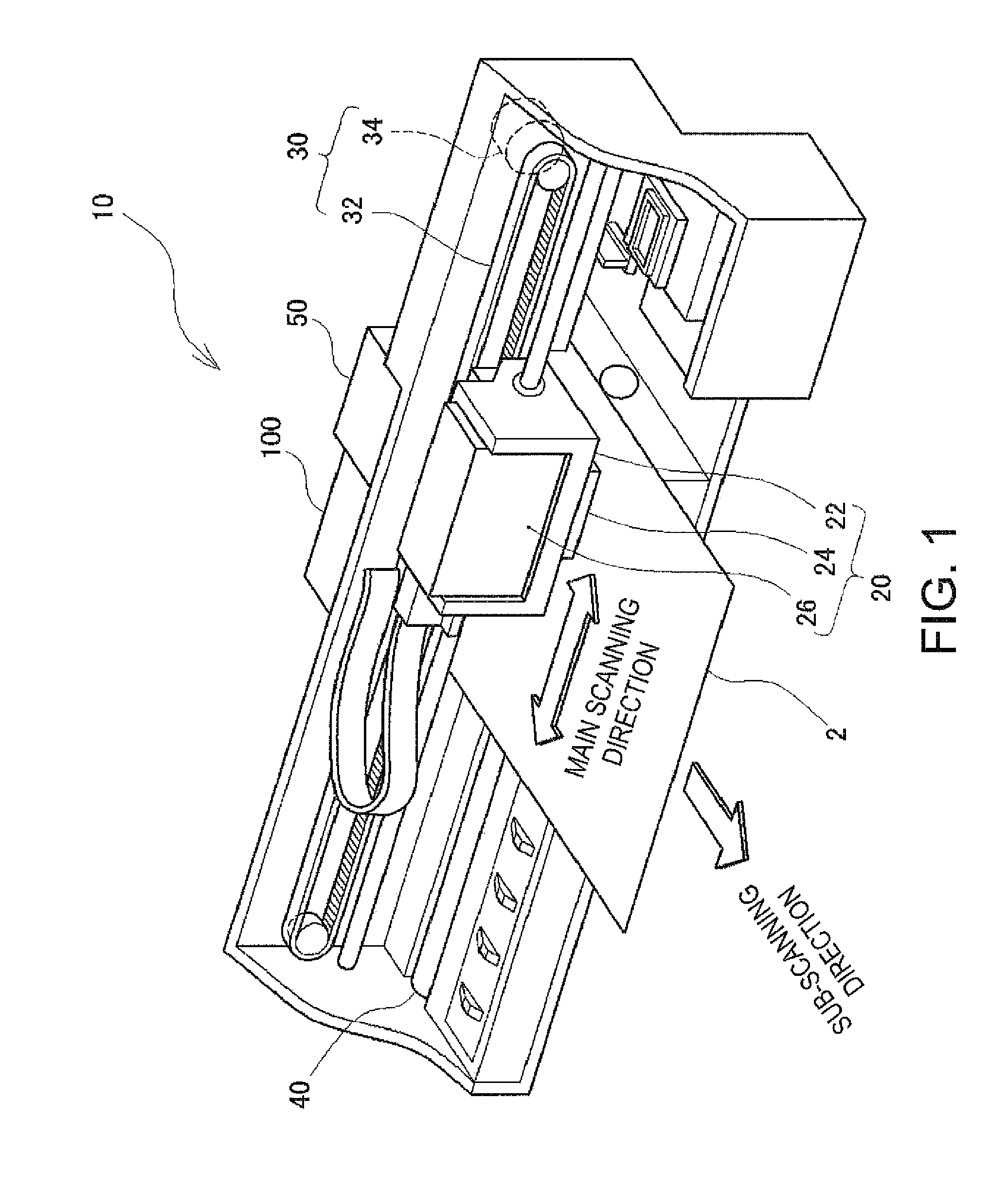
[0072]In the example described above, the explanation is presented assuming that the ink is ejected from the ejection nozzle 200 by applying the drive signal to the piezoelectric element 204. However, according to the method of the present embodiment, since the drive signal can flexibly be changed in accordance with the timing of switching ON / OFF of the gate element 302, it is also possible to apply the drive signal with which the ink is not ejected from the nozzle 200.

[0073]FIG. 8 is an explanatory diagram exemplifying the drive signal to be applied to the piezoelectric element 204 in a first modified example. In the example shown in the drawing, the gate element 302 is switched ON at the timing (the time t1) at which the voltage of the reference voltage waveform rises to the initial voltage Vini, and then the gate element 302 is switched OFF at the timing (the time t18) at which the voltage rises a little bit to reach the voltage V4. Then, after keeping ...

second modified example

D-2. Second Modified Example

[0075]Further, in the embodiment described above, the reference voltage waveform is repeatedly output at the repetition period Tp, and the drive signal is applied by switching ON / OFF of the gate element 302 at appropriate timings while the reference voltage waveform is output for a plurality of cycles. Therefore, by shifting the timing of switching ON / OFF of the gate element 302 by one cycle of the reference voltage waveform, the timing of ejecting the ink from the ejection nozzle 200 can also be shifted.

[0076]FIG. 9 is an explanatory diagram exemplifying how the timing of ejecting the ink from the ejection nozzle 200 is shifted in a second modified example. Although the drive signal shown in FIG. 9 is the same as the drive signal described above using FIG. 6, in the example shown in FIG. 9, the drive signal is delayed by one cycle of the reference voltage waveform compared to the case shown in FIG. 6. It is obvious that the drive signal can be applied at...

third modified example

D-3. Third Modified Example

[0077]Further, in the embodiment or the modified examples described above, the explanation is presented assuming that there is used the reference voltage waveform shown in FIG. 5, namely the waveform with the voltage linearly rising from the lower-limit voltage Vmin to the upper-limit voltage Vmax in a period (Tr≈0.5Tp) roughly a half of the repetition period Tp, and then linearly dropping from the upper-limit voltage Vmax to the lower-limit voltage Vmin in the remaining repetition period, namely a period (Tf≈0.5Tp) roughly a half of the repetition period Tp. However, the reference voltage waveform is not limited to such a waveform, but a variety of waveforms can be used as the reference voltage waveform.

[0078]FIGS. 10A and 10B are explanatory diagrams exemplifying a variety of reference voltage waveforms. For example, in the reference voltage waveform shown in FIG. 10A, the voltage slowly rises from the lower-limit voltage Vmin to the upper-limit voltage ...


PUM


Abstract

A reference voltage waveform reciprocating between a first voltage and a second voltage is supplied to a piezoelectric element via a switch. If a switch is set to a connected state (ON), the reference voltage waveform is applied to the piezoelectric element, and if the switch is set to a disconnected state (OFF), the voltage when the switch is set to OFF continues to be applied. Therefore, it becomes possible to apply a variety of drive signals only by switching the switch in accordance with increase and decrease of the reference voltage waveform, and there is no need to store a plurality of types of drive signals. Further, it is possible to start to apply the drive signal immediately when the voltage of the reference voltage waveform reaches the target voltage.

Description

BACKGROUND[0001]1. Technical Field[0002]The present invention relates to a technology for applying a drive signal to thereby drive a piezoelectric element.[0003]2. Related Art[0004]There has been known a fluid ejection device, such as an inkjet printer, for applying a drive signal to a piezoelectric element as a capacitive load to thereby eject a fluid such as ink. The fluid ejection device is equipped with a drive circuit, and applies the drive signal generated by the drive circuit to thereby drive the piezoelectric element. Further, since the piezoelectric element extends or contracts in accordance with the voltage applied thereto, by switching the drive signal to be applied to the piezoelectric element, the ejection conditions (e.g., an ejection amount) of the fluid can be switched.[0005]Therefore, there is proposed a technology of repeatedly outputting a plurality of types of drive signals (e.g., drive signals A, B, and C) in series and then switching the drive signal to be sele...

Claims


Application Information

Patent Timeline
Patent Type & Authority Applications(United States)
IPC IPC(8): B41J29/38
CPCB41J2/04541B41J2/04588B41J2/04581B41J2/04596
Inventor OSHIMA, ATSUSHITABATA, KUNIOMIYAZAKI, SHINICHIIDE, NORITAKAYOSHINO, HIROYUKI
Owner SEIKO EPSON CORP
Why Eureka
Try Eureka