Method of measuring cut-off wavelength of optical fiber

a technology of optical fiber and cut-off wavelength, which is applied in the field of optical fiber cut-off wavelength measurement, can solve the problems of difficult to accurately calculate the cut-off wavelength, and difficult to remove the higher order mode, so as to achieve the effect of improving the accuracy at the time of generating the cut-off wavelength

Inactive Publication Date: 2012-10-18
THE FUJIKURA CABLE WORKS LTD
View PDF2 Cites 2 Cited by
  • Summary
  • Abstract
  • Description
  • Claims
  • Application Information

AI Technical Summary

Benefits of technology

[0109]Accordingly, even in a case where there is a large error between the predicted cut-off wavelength and the actual cut-off wavelength of a single mode fiber or a low-bending loss fiber, which is generally used for communication, to be measured, a unique advantage of the present invention can be acquired.
[0110]More specifically, a condition that the length of the reference fiber at the time of measuring the power of transmission light transmitted through the reference fiber is adjusted such that the reference fiber propagates only light of the base mode at the predicted cut-off wavelength of the measurement target fiber, can be reliably satisfied.
[0111]In addition, a condition that the length of the reference fiber is adjusted such that the cut-off wavelength of the reference fiber is shorter than the predicted cut-off wavelength of the measurement target fiber by at least 10 nm, can be reliably satisfied.
[0112]As a result, the accuracy at the time of generating the cut-off wavelength can be further improved.
[0113]However, the difference between the lengths at the time of measuring the reference fiber and the measurement target fiber may be 1.3 or more as a difference between the logarithmic values of the lengths of the fibers due to the slope of a steep inclination that can be checked when the wavelength dependence represented as the ratio of the power of transmission light transmitted through the measurement target fiber to the power of transmission light transmitted through the reference fiber, which are actually measured, is represented as a graph.
[0114]Since such a difference occurs due to the refractive index profile of the fiber, it can be estimated by acquiring the relationship between the cut-off wavelength of the measurement target fiber and the length of the measurement target fiber based on the refractive index profile of the measurement target fiber.

Problems solved by technology

In such low-bending loss optical fibers, the confinement effect is also increased for a higher order mode, and accordingly, it is difficult to remove the higher order mode with the degree of bending that is applied in the bending method.
Accordingly, it is difficult to calculate the cut-off wavelength with accuracy in the bending method.
However, in the cut-off wavelength measurement according to the multi-mode excitation method, there are the following problems.
Accordingly, there is a case where it is difficult to accurately calculate a cut-off wavelength.
Accordingly, in the proposal disclosed in “2009 Processing 2 of the Society Conference of the Institute of Electronics, Information and Communication Engineers, Page 190, Proposal of Reliable Cut off Wavelength Measurement for Bend Insensitive Fiber”, such problems are not considered, and, accordingly, there is concerned that accurate measurement cannot be performed.
Consequently, in a practical measurement site, it cannot be determined that an appropriate reference fiber can be easily prepared in the single mode fiber reference method.

Method used


Image

  • Method of measuring cut-off wavelength of optical fiber
  • Method of measuring cut-off wavelength of optical fiber
  • Method of measuring cut-off wavelength of optical fiber

Examples


experimental example 1

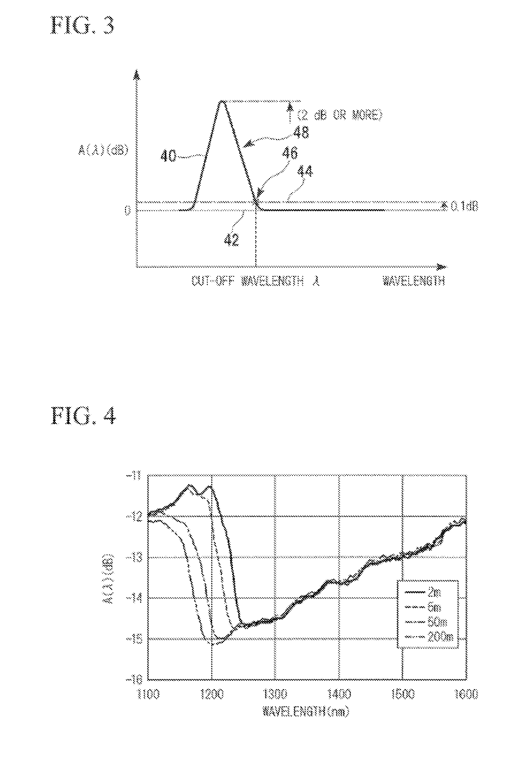
[0218]The results of a test are illustrated in FIG. 4 showing that the cut-off wavelength of the single mode fiber acquired by measurement changes in accordance with the length of a fiber used in the measurement, in other words, the cut-off wavelength is shortened as the length of the fiber is increased is illustrated in FIG. 4.

[0219]In this experiment, a general single mode fiber used for communication was used as the measurement target fiber, and the power Psig(λ) of transmission light transmitted through the measurement target fiber that was formed by a single mode fiber of various kinds of lengths (2 m to 200) and the power Pref(λ) of transmission light transmitted through the reference fiber having a constant length were measured according to the multi-mode excitation method.

[0220]The wavelength dependency of the ratio A(λ) on the length of the fiber when the ratio A(λ) of the transmission light power Psig(λ) to the transmission light power Pref(λ) was measured is illustrated i...

experimental example 2

[0228]In Experimental Example 2, a measurement target fiber, which has a length of 2 m, configured of a single mode fiber formed by a strand drawn by using the same base material as the base material used for manufacturing the fiber used in Experimental Example 1 will be described.

[0229]In addition, a fiber, which has a length of 200 m, formed by a strand drawn by using the same base material as the base material used for manufacturing the measurement target fiber was used as the reference fiber.

[0230]Next, the power Psig(λ) of transmission light transmitted through the measurement target fiber and the power Pref(λ) of transmission light transmitted through the reference fiber were measured by using the method of the present invention, and the ratio A(λ) of the transmission light power Psig(λ) to the transmission light power Pref(λ) was measured.

[0231]The wavelength dependency of the transmission light power ratio A(λ) at this time is illustrated in FIG. 6.

[0232]In this case, as is ...

experimental example 3

[0239]In Experimental Example 3, a measurement target fiber, which has a length of 22 m, configured of a single mode fiber formed by a low-bending loss fiber will be described.

[0240]In addition, as the reference fiber, a fiber, which has a length of 200 m, formed by a strand drawn by using the same base material as the base material used for manufacturing the measurement target fiber is used.

[0241]Next, the power Psig(λ) of transmission light transmitted through the measurement target fiber and the power Pref(λ) of transmission light transmitted through the reference fiber were measured by using the method of the present invention, and the ratio A(λ) of the transmission light power Psig(λ) to the transmission light power Pref(λ) was measured.

[0242]The wavelength dependency of the transmission light power ratio A(λ) at this time is denoted by a solid line illustrated in FIG. 7.

[0243]In addition, in Experimental Example 3, as a predicted cut-off wavelength of the measurement target fi...


PUM

PropertyMeasurementUnit
cut-off wavelengthaaaaaaaaaa
lengthaaaaaaaaaa
lengthaaaaaaaaaa

Abstract

A cut-off wavelength measuring method according to the present invention includes: preparing a single mode fiber as a reference fiber; preparing a measurement target fiber; adjusting the length of the single mode fiber such that the length of the single mode fiber is longer than the that of the measurement target fiber at the time of measuring power of transmission light and the reference fiber propagates only light of a base mode at a predicted cut-off wavelength of the measurement target fiber; measuring wavelength dependence of power of light transmitted through the reference fiber and wavelength dependence of power of light transmitted through the measurement target fiber; and calculating a cut-off wavelength of the measurement target fiber based on wavelength dependence represented as the ratio of the power of transmission light transmitted through the measurement target fiber to the power of light transmitted through the reference fiber.

Description

CROSS-REFERENCE TO RELATED APPLICATION[0001]This application is based on and claims priority from Japanese Patent Application No. 2011-085520, filed on Apr. 7, 2011, the contents of which are incorporated herein by reference.BACKGROUND OF THE INVENTION[0002]1. Field of the Invention[0003]The present invention relates to a silica-based optical fiber that is used for optical fiber communication, and more particularly, to a method of measuring a minimum wavelength of a single-mode fiber for which the propagation mode is single, that is, a cut-off wavelength in the fiber.[0004]2. Background Art[0005]As a conventional method of measuring the cut-off wavelength of a single mode fiber, particularly, as a method of measuring an effective cut-off wavelength, for example, as illustrated in “Opto-electronic Measuring Instruments Guide, Thoroughly-Revised Edition”, Optronics Co., Ltd., Published on Jun. 24, 2004, a bending method and a multi-mode excitation method are known.[0006]In the bending...

Claims


Application Information

Patent Timeline
Patent Type & Authority Applications(United States)
IPC IPC(8): G01N21/17
CPCG01N21/84G01M11/33G02B6/02
Inventor SUGIMOTO, YASUKOMATSUO, SHOICHIRO
Owner THE FUJIKURA CABLE WORKS LTD
Why Eureka
Try Eureka