Six degree-of-freedom laser tracker that cooperates with a remote projector to convey information

a laser tracker and remote projector technology, applied in the direction of distance measurement, instruments, using reradiation, etc., can solve the problem that the absolute distance meter was too slow to accurately find the position of a moving targ

Active Publication Date: 2012-10-18
FARO TECH INC
View PDF8 Cites 57 Cited by
  • Summary
  • Abstract
  • Description
  • Claims
  • Application Information

AI Technical Summary

Benefits of technology

[0010]According to an embodiment of the present invention, a method of measuring three or more surface sets on an object surface with a coordinate measurement device and a target scanner, each of the three of more surface sets being three-dimensional coordinates of a point on the object surface in a device frame of reference, each surface set including three values, the device frame of reference being associated with the coordinate measurement device. The method includes the steps of: providing the target scanner having a body, a first retroreflector, a projector, a camera, and a scanner processor, wherein the first retroreflector, projector, and camera are rigidly affixed to the body, and the target scanner is mechanically detached to the coordinate measurement device, wherein the projector includes a source pattern of light and a projector lens, the source pattern of light located on a source plane and including at least three non-collinear pattern elements, the projector lens configured to project the source pattern of light onto the object to form an object pattern of light on the object, each of the at least three non-collinear pattern elements corresponding to at least one surface set, wherein the camera includes a camera lens and a photosensitive array, the camera lens configured to image the object pattern of light onto the photosensitive array as an image pattern of light, the photosensitive array including camera pixels, the photosensitive array configured to produce, for each camera pixel, a corresponding pixel digital value responsive to an amount of light received by the camera pixel from the image pattern of light. The method also includes: providing the coordinate measurement device, the coordinate measurement device configured to measure a translational set and an orientational set, the translational set being values ...

Problems solved by technology

Prior to the '446 patent, absolute distance meters were...

Method used


Image

  • Six degree-of-freedom laser tracker that cooperates with a remote projector to convey information
  • Six degree-of-freedom laser tracker that cooperates with a remote projector to convey information
  • Six degree-of-freedom laser tracker that cooperates with a remote projector to convey information

Examples


Embodiment Construction

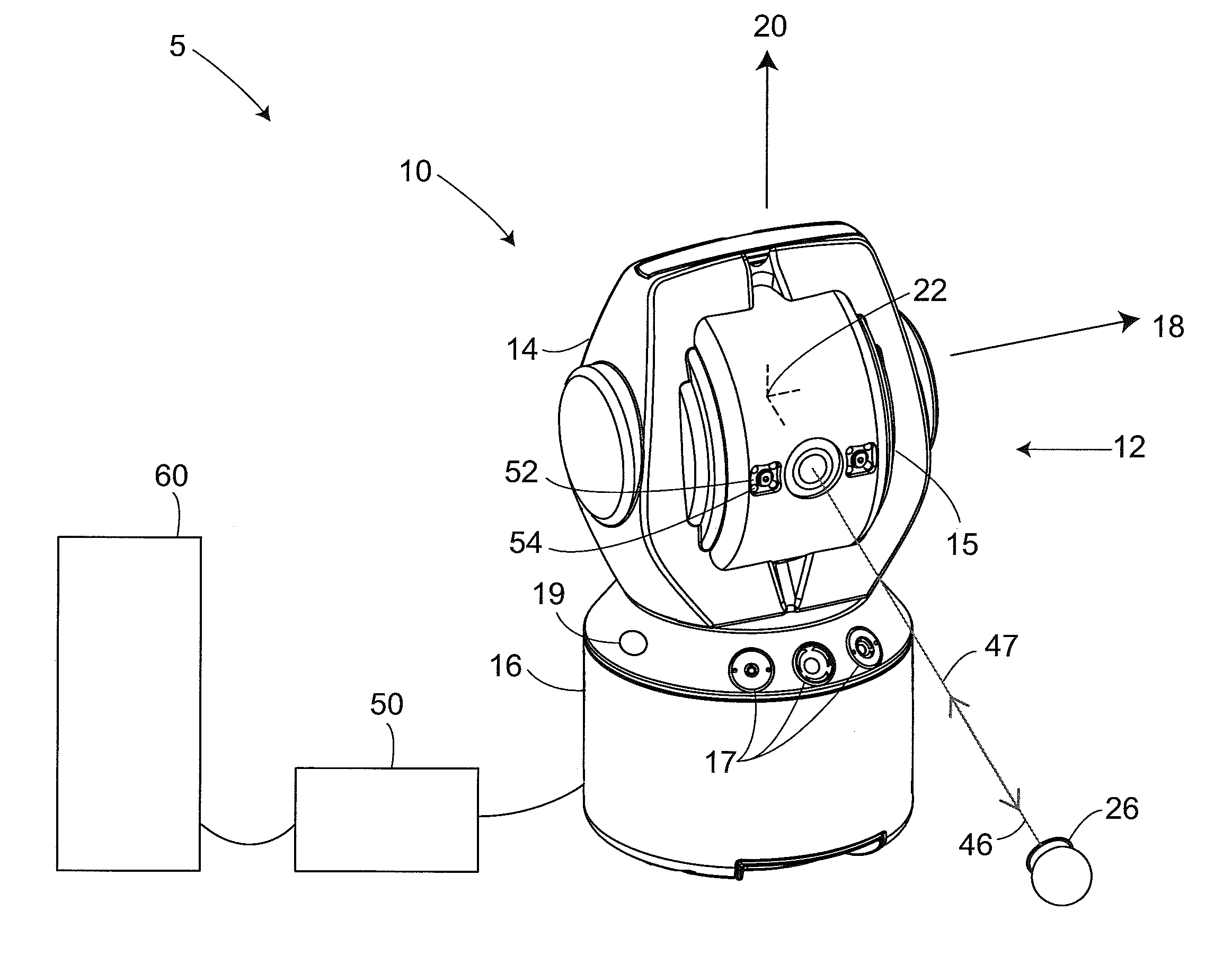
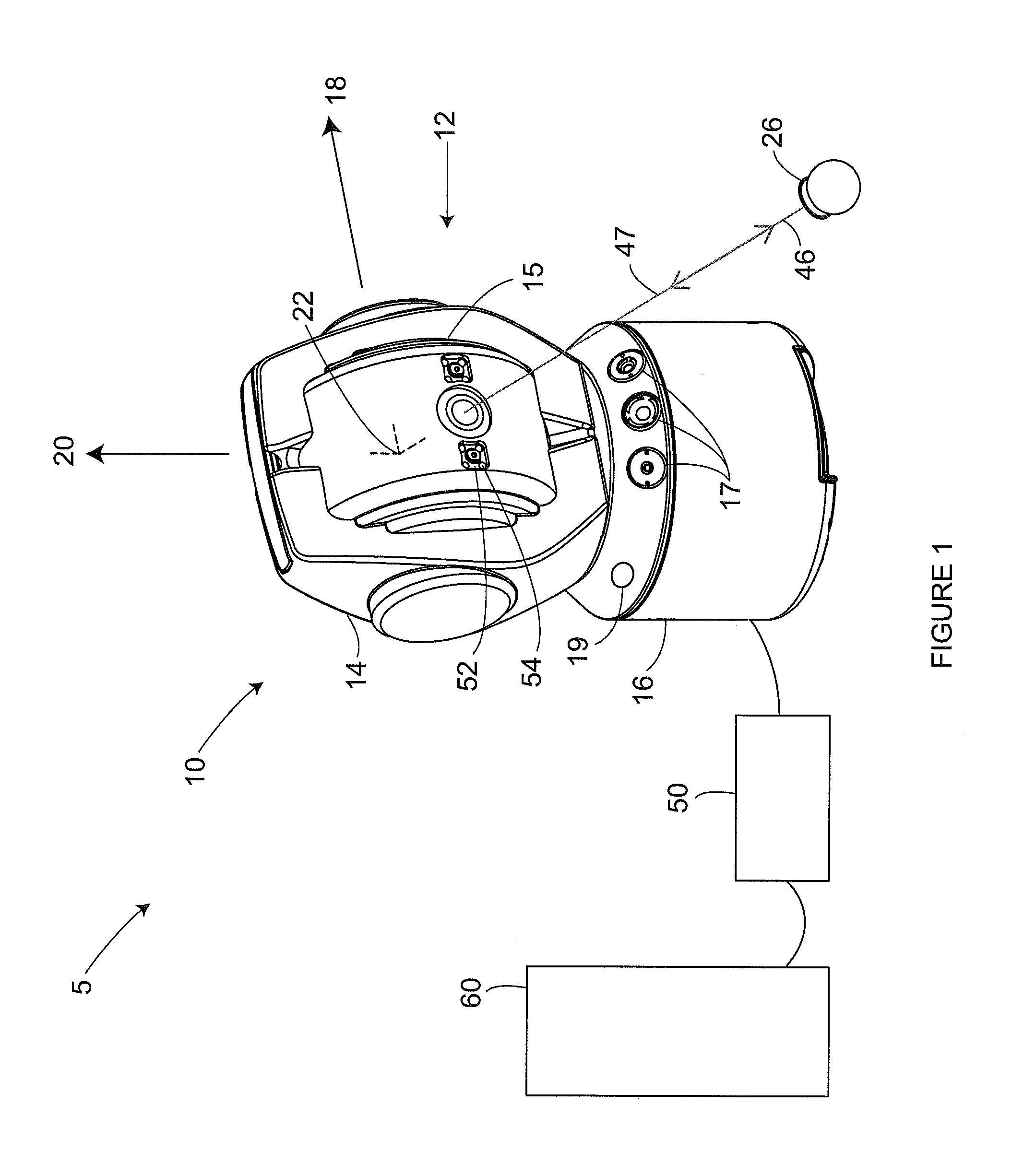
[0050]An exemplary laser tracker system 5 illustrated in FIG. 1 includes a laser tracker 10, a retroreflector target 26, an optional auxiliary unit processor 50, and an optional auxiliary computer 60. An exemplary gimbaled beam-steering mechanism 12 of laser tracker 10 comprises a zenith carriage 14 mounted on an azimuth base 16 and rotated about an azimuth axis 20. A payload 15 is mounted on the zenith carriage 14 and rotated about a zenith axis 18. Zenith axis 18 and azimuth axis 20 intersect orthogonally, internally to tracker 10, at gimbal point 22, which is typically the origin for distance measurements. A laser beam 46 virtually passes through the gimbal point 22 and is pointed orthogonal to zenith axis 18. In other words, laser beam 46 lies in a plane approximately perpendicular to the zenith axis 18 and that passes through the azimuth axis 20. Outgoing laser beam 46 is pointed in the desired direction by rotation of payload 15 about zenith axis 18 and by rotation of zenith c...


PUM


Abstract

A method of conveying information to a user of a coordinate measurement device, includes providing a first target projector, sending a first light beam from the device to a retroreflector; receiving a second light beam from the retroreflector; measuring the orientational and translational sets, the translational set based on the second light beam; selecting first information to be conveyed from the group consisting of one or more positions on the object, a direction indicated by a moving pattern, a message that includes one or more symbols or alphanumeric characters, a hidden feature, a measured object characteristic, a modeled characteristic, a magnified representation of surface characteristics, a pattern having meaning according to a rule, and combinations thereof; determining a first light pattern corresponding to the information; storing the first light pattern; and projecting the first light pattern onto the object based on the translational and orientational sets.

Description

CROSS REFERENCE TO RELATED APPLICATIONS[0001]The present application claims the benefit of U.S. Provisional Patent Application No. 61 / 592,049 filed Jan. 30, 2012, and U.S. Provisional Patent Application No. 61 / 475,703 filed Apr. 15, 2011, the entire contents of both of which are hereby incorporated by reference.BACKGROUND[0002]The present disclosure relates to a coordinate measuring device. One set of coordinate measurement devices belongs to a class of instruments that measure the three-dimensional (3D) coordinates of a point by sending a laser beam to the point. The laser beam may impinge directly on the point or on a retroreflector target in contact with the point. In either case, the instrument determines the coordinates of the point by measuring the distance and the two angles to the target. The distance is measured with a distance-measuring device such as an absolute distance meter or an interferometer. The angles are measured with an angle-measuring device such as an angular ...

Claims


Application Information

Patent Timeline
IPC IPC(8): G01B11/14G16Z99/00
CPCG01C15/002G01S7/4808G01S7/4813G01S7/4818G01C3/08G01S17/42G01S17/66G01S17/89G01S7/491G16Z99/00G06F17/40G01B11/00G01B11/02G01B11/03G01S7/481G01S7/42G01B5/012G01B11/25G01B11/27
Inventor BRIDGES, ROBERT E.PARKER, DAVID H.
Owner FARO TECH INC
Why Eureka
Try Eureka