
Method for determining eccentricity of optical disc

a technology of eccentricity and optical disc, applied in the direction of digital signal error detection/correction, instruments, recording signal processing, etc., can solve the problems of light beams, optical disc may fail to form effective tracking error control signals, and unsatisfactory manufacturing control

Inactive Publication Date: 2012-10-18
QUANTA STORAGE INC
View PDF10 Cites 0 Cited by
  • Summary
  • Abstract
  • Description
  • Claims
  • Application Information

AI Technical Summary

Benefits of technology

"The present invention provides a method for quickly determining the eccentricity of an optical disc. This is done by measuring the ratio between minimum and maximum amplitudes of TE signals of a plurality of known eccentric distance optical discs, and comparing it with an established eccentric distance ratio table or curve. This method allows for the accurate and efficient determination of the eccentricity of an optical disc, which can aid in the manufacturing process and ensure the quality of the finished product."

Problems solved by technology

An eccentric optical disc being rotated with a high speed in an optical disc drive brings vigorous displaced vibrations, such that light beams projected from the optical disc drive to the optical disc may fail to form effective tracking error (TE) control signals.
Caused by possible unsatisfactory manufacturing control procedures of the optical disc 1, an eccentric optical disc 1 is much likely resulted.
Consequently, a data read process of the optical disc drive according to the TE signals along the data tracks 2 becomes complicated and even infeasible due to excessively displaced revolutions.
However, stable TE signals are difficult to get due to displaced vibrations during revolutions of an eccentric optical disc.
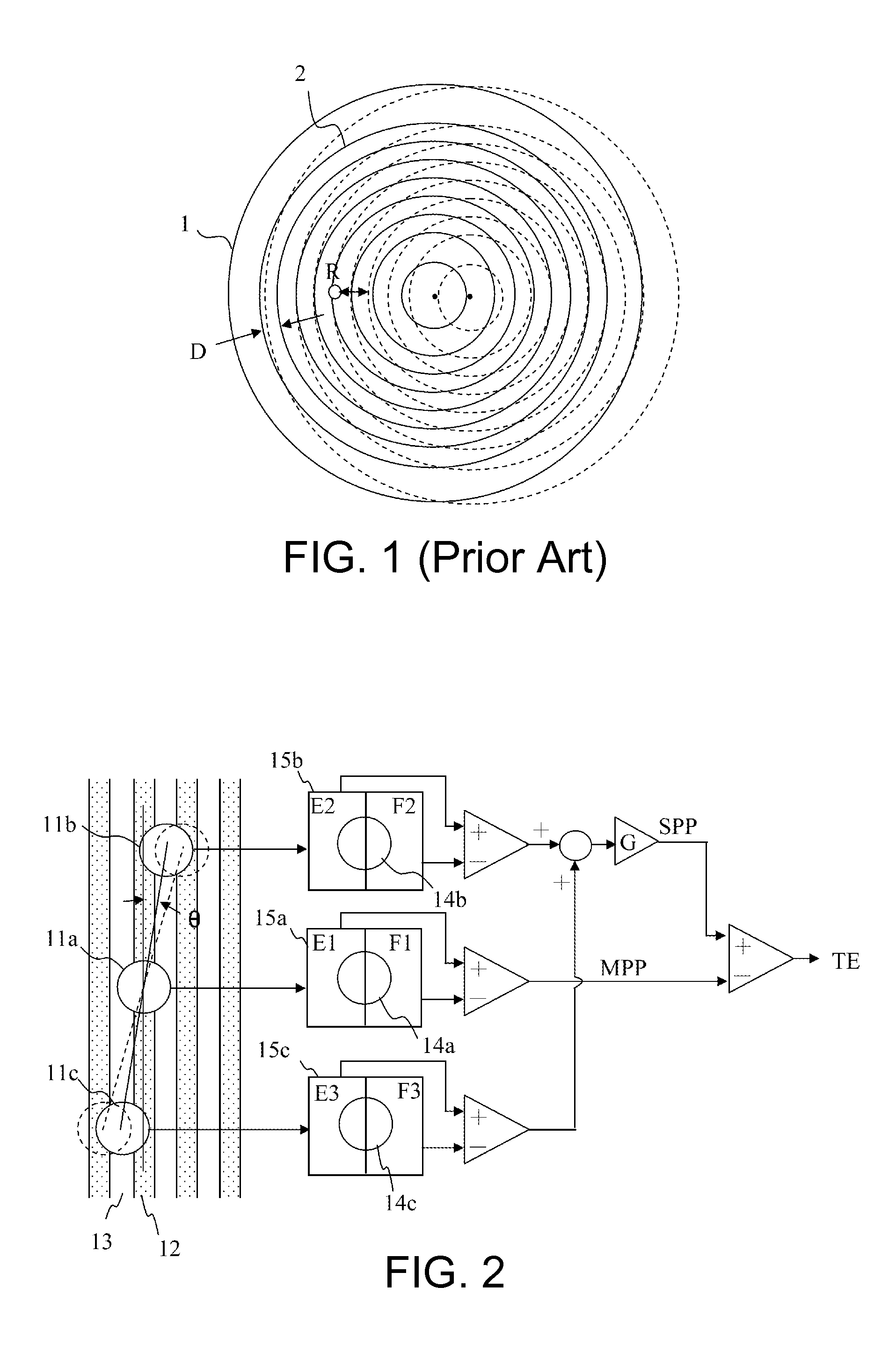
In the prior art, the count of unstable TE signals serves as basis for calculating the eccentric distance of the optical disc, and so an eccentric distance obtained through such approach is rather questionable and is also unsuitable for subsequent adjustments on control parameters and reading / writing controls of the optical disc drive.

Method used


Image

  • Method for determining eccentricity of optical disc
  • Method for determining eccentricity of optical disc
  • Method for determining eccentricity of optical disc

Examples


Embodiment Construction

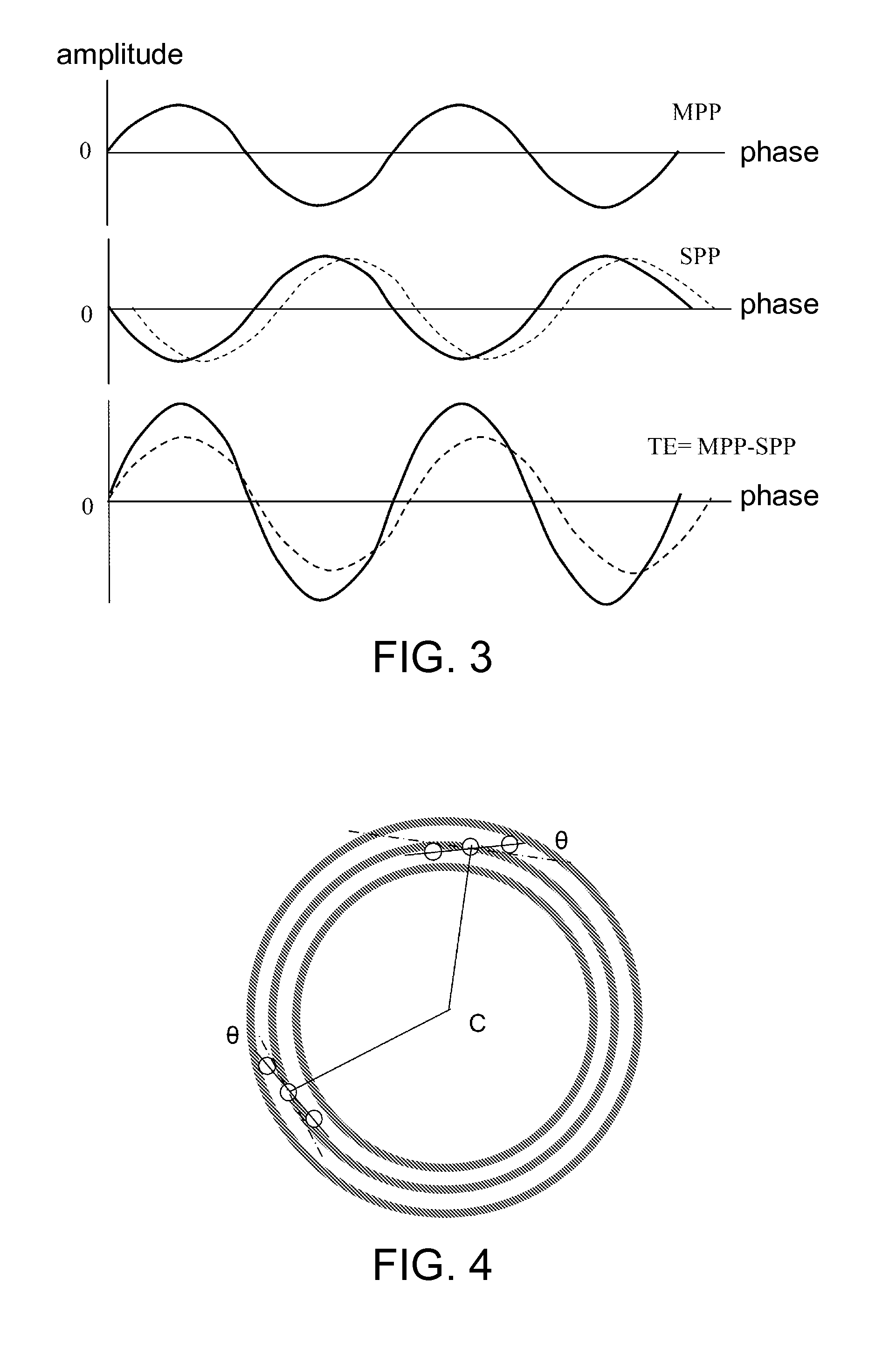
[0023]Referring to FIGS. 2 and 3, FIG. 2 shows a functional block diagram of an optical disc drive generating a TE signal, and FIG. 3 shows a schematic diagram of a TE signal. When the optical disc performs track control via differential push-pull (DPP), a pickup head focuses laser beams to a main light beam 11a and two secondary light beams 11b and 11c, which are respectively projected to a data groove 12 and two lands 13. The projected light beams are reflected by an optical disc into reflected beam spots 14a, 14b and 14c, which are then respectively projected to a main optical transducer 15a and two secondary optical transducers 15b and 15c. The optical transducers 15a, 15b and 15c are respectively divided into two same-sized sub-units E and F, and convert light flux at the reflected beam spots 14a, 14b and 14c into corresponding electric signals. The electric signal E1-F1 of two sub-units of the main optical transducer 15a forms a main push-pull (MPP) signal. The electric signal...


PUM

PropertyMeasurementUnit
eccentric distancesaaaaaaaaaa
distancesaaaaaaaaaa
eccentric distanceaaaaaaaaaa

Abstract

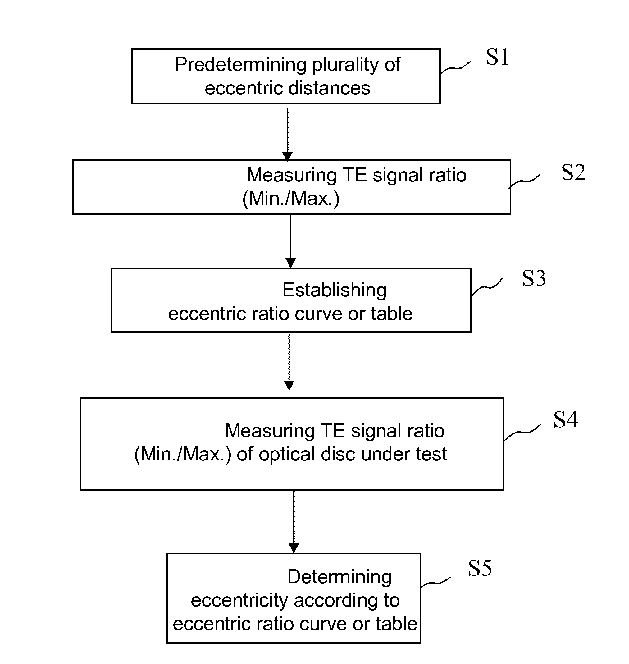
A method for determining an eccentricity of an optical disc is provided. The method includes predetermining a plurality of optical disc with known eccentric distances, respectively measuring a ratio of maximum and minimum amplitudes of a tracking error signal of the optical discs, establishing an eccentric distance ratio table or curve, measuring a ratio of maximum and minimum amplitudes of the tracking error signal for an optical disc under test, and comparing the measured ratio with the table or curve to promptly determine the eccentricity distance of the optical disc under test.

Description

[0001]This application claims the benefit of Taiwan application Serial No. 100112740, filed Apr. 12, 2011, the subject matter of which is incorporated herein by reference.BACKGROUND OF THE INVENTION[0002]1. Field of the Invention[0003]The invention relates in general to a method for determining an eccentricity of an optical disc under test for an optical disc drive, and more particularly to a method for determining an eccentricity of an optical disc for adjusting control parameters of an optical disc drive.[0004]2. Description of the Related Art[0005]An eccentric optical disc being rotated with a high speed in an optical disc drive brings vigorous displaced vibrations, such that light beams projected from the optical disc drive to the optical disc may fail to form effective tracking error (TE) control signals. The TE signals are for controlling beam spots to focus at the optical disc and move along data tracks in order to correctly read data in the optical disc.[0006]FIG. 1 shows a ...

Claims


Application Information

Patent Timeline
Patent Type & Authority Applications(United States)
IPC IPC(8): G11B7/00
CPCG11B7/0903G11B7/24097G11B7/0953
Inventor HSUEH, MING-HUAHSIAO, YI-LONG
Owner QUANTA STORAGE INC
Learn More